CCKW Fuel Truck Rebuild - January, 2024:
The team at MilSpec Vehicle Restoration in Belvidere, New Jersey focused most of their attention this month on completing the rebuild and repainting of the CCKW Fuel Truck’s 6-cylinder GMC 270 engine, whilst also diverting a little energy to smaller details on the vehicle’s chassis.
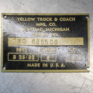
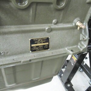
The engine's original data plate following refurbishing and repainting. Note how the engine was manufactured by the Yellow Truck & Coach Manufacturing Company, a partially-owned subsidiary of General Motors until 1943 when it was fully merged into the parent company's operations. (photo via Mil-Spec Restoration)
Chassis:
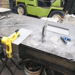
The team refurbished the steel structure which holds the vehicle’s battery in place. The rear plate on this component needed replacing due to significant corrosion issues. They cut away the damaged part, fabricated a replacement and then welded it in place. Next they trial-fitted the assembly onto the vehicle’s chassis to ensure proper alignment before welding on an appropriate length of retaining angle along its bottom edge. After repainting, the fully restored ‘battery box’ was remounted on the vehicle.
The restoration team also installed a set of new rubber bumper blocks (with freshly overhauled and repainted housings) onto each of the trucks three axles.
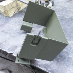
The battery box in the process of being welded back together with a newly-fabricated rear plate. (photo via Mil-Spec Restoration)
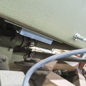
A view of the chassis wall, with the bare steel battery tray trial fitted to its reverse side. Note the flexible hydraulic line for the braking system is also in view. (photo via Mil-Spec Restoration)
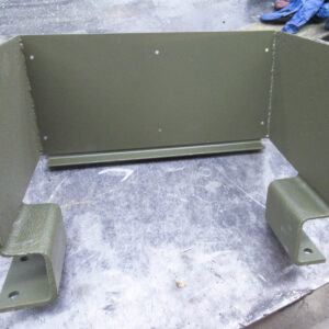
A view of the newly-rebuilt battery tray enclosure following repainting. (photo via Mil-Spec Restoration)
Engine:
Engine reassembly really picked up steam this month. This effort began with the cam shaft. With its timing gear pressed onto the front end, the cam shaft assembly slid into the engine block. Tappets were placed in the engine block openings above each of the cam shaft’s six cams. Next the team installed the push rods, sliding them vertically into position above each tappet, with the rocker shaft mounted above. These components are essential elements of the mechanism which opens and closes the intake and exhaust valves with precise timing.
Essentially, the cam shaft rotates in sync with the engine’s crank shaft. The six cams along its length each nudge a tappet at the lower end of each push rod, which then agitates the rocker shaft above to appropriately position the engine intake and exhaust valves in sequence with the combustion process. Each stage requires careful adjustment, of course, but when working properly, this whole cycle repeats continuously during engine operation. Images from the engine overhaul manual are reproduced again below to show some of these details.
A close up of the timing gear attached to one end of the crank shaft. It meshes with a larger gear connected to the cam shaft, not presently installed here.
A image from the GM-270 engine overhaul manual showing its crank shaft. The connecting rods for each piston attach at each position marked with an "E". The crank shaft mounts to the engine block bearings at each of the four journals (A, B, C & D).
A view of the cylinder head showing the valves in position. Note the push-rods are also installed in this shot. These are pushed up and down by the cam shaft below, and their motion, in turn, adjusts the position of the rocker arm which manipulates the valves. During engine operation, the push rods cavity is covered with a plate, engine coolant flowing within.
Oil Pan Installation:
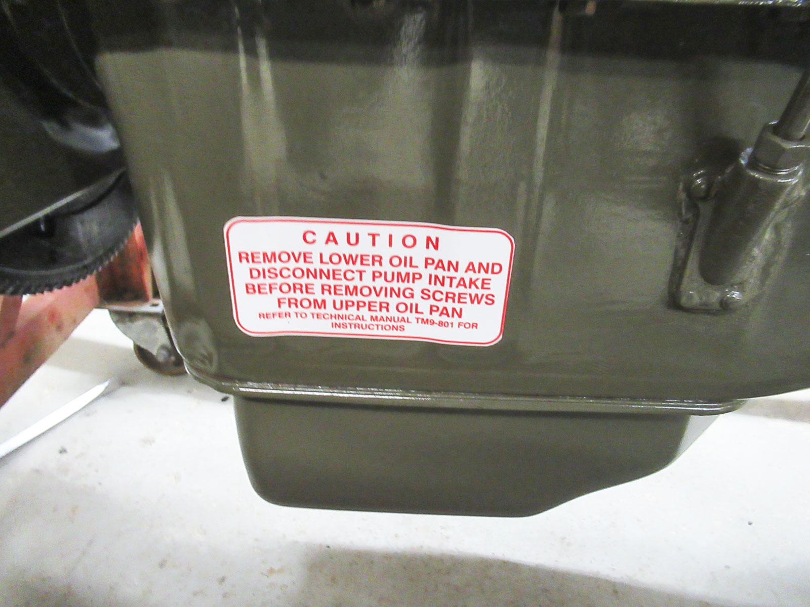
With the above key items installed, the rebuild team then installed the oil pump in the crank case and new seals for the front cover. The upper oil pan was then installed to the bottom face of the crank case, along with its internal oil pump supply tube.
A new gasket was then fabricated for the engine’s lower oil pan, which was then screwed to the engine, each steel fastener torqued down evenly against copper washers, which deform to both help lock the bolts in place and improve the seal.
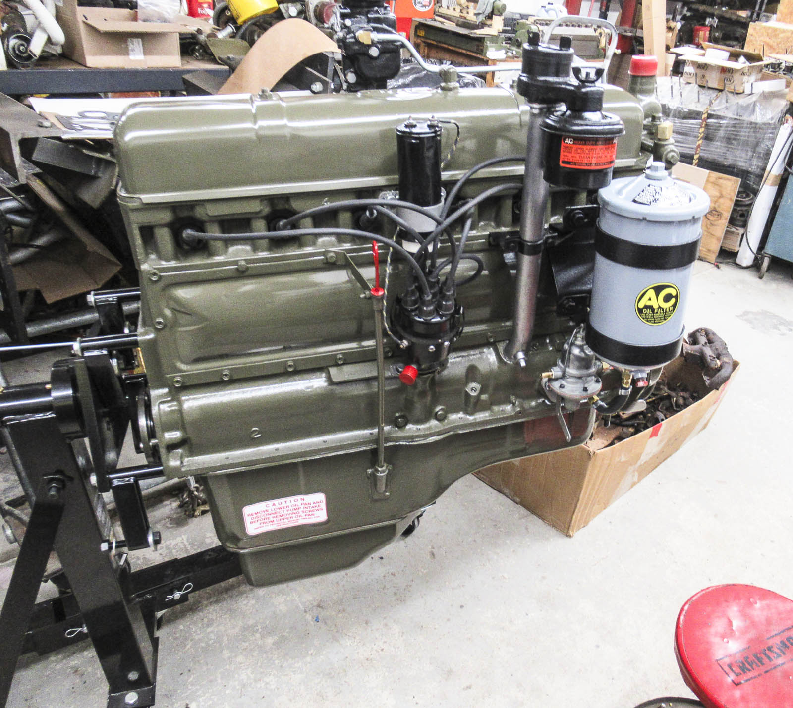
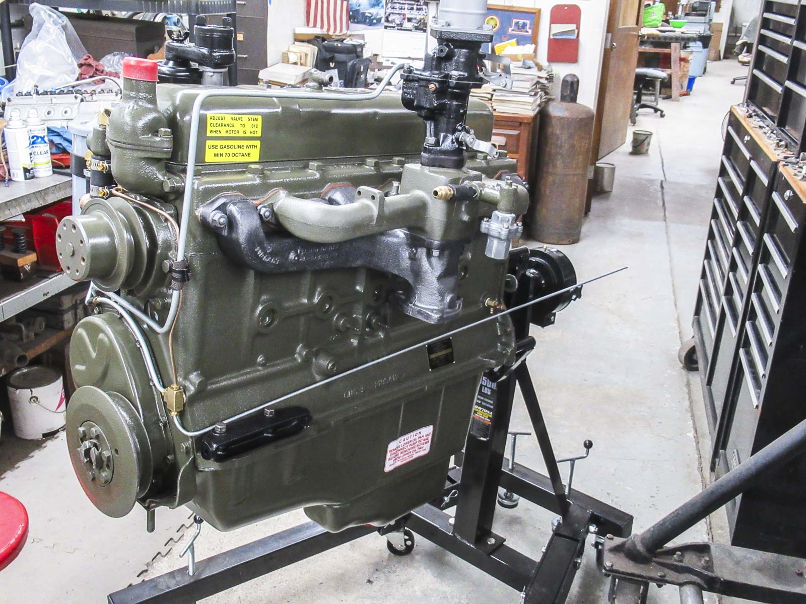
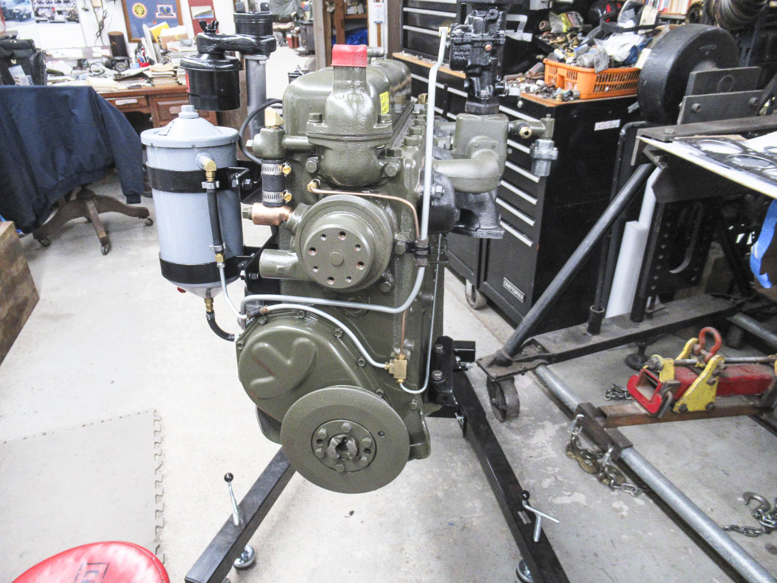
The crankshaft pulley was then installed to the front of the engine. This component is connected to the crankshaft; it powers the flexible belts which drive the cooling fan and generator. Numerous additional components and ancillary systems were also installed on the engine, from the carburetor, oil filter, fuel and water pumps (with their associated piping), the distributor, spark plugs and ignition lines and intake/exhaust manifolds, etc.
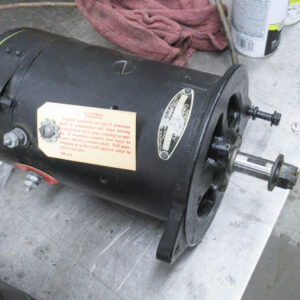
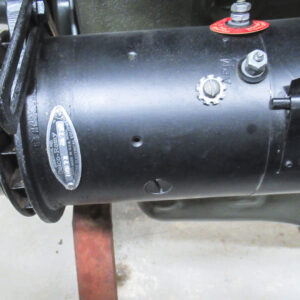
The engine's freshly overhauled generator prior to installation. This device is like an electric motor in reverse, converting rotational movement into electric current for charging up the battery. (photo via Mil-Spec Restoration)
The generator mounted back in place on the engine. It generates electrical current for charging the battery via a drive belt connected to the engine's crank shaft pulley. (photo via Mil-Spec Restoration)
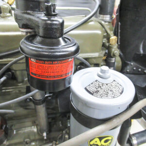
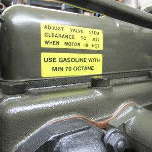
Maintenance decals applied to the crank case air filter housing (orange) and the oil filter assembly (black). Note the distributor cap at bottom left. (photo via Mil-Spec Restoration)
Engine Testing:
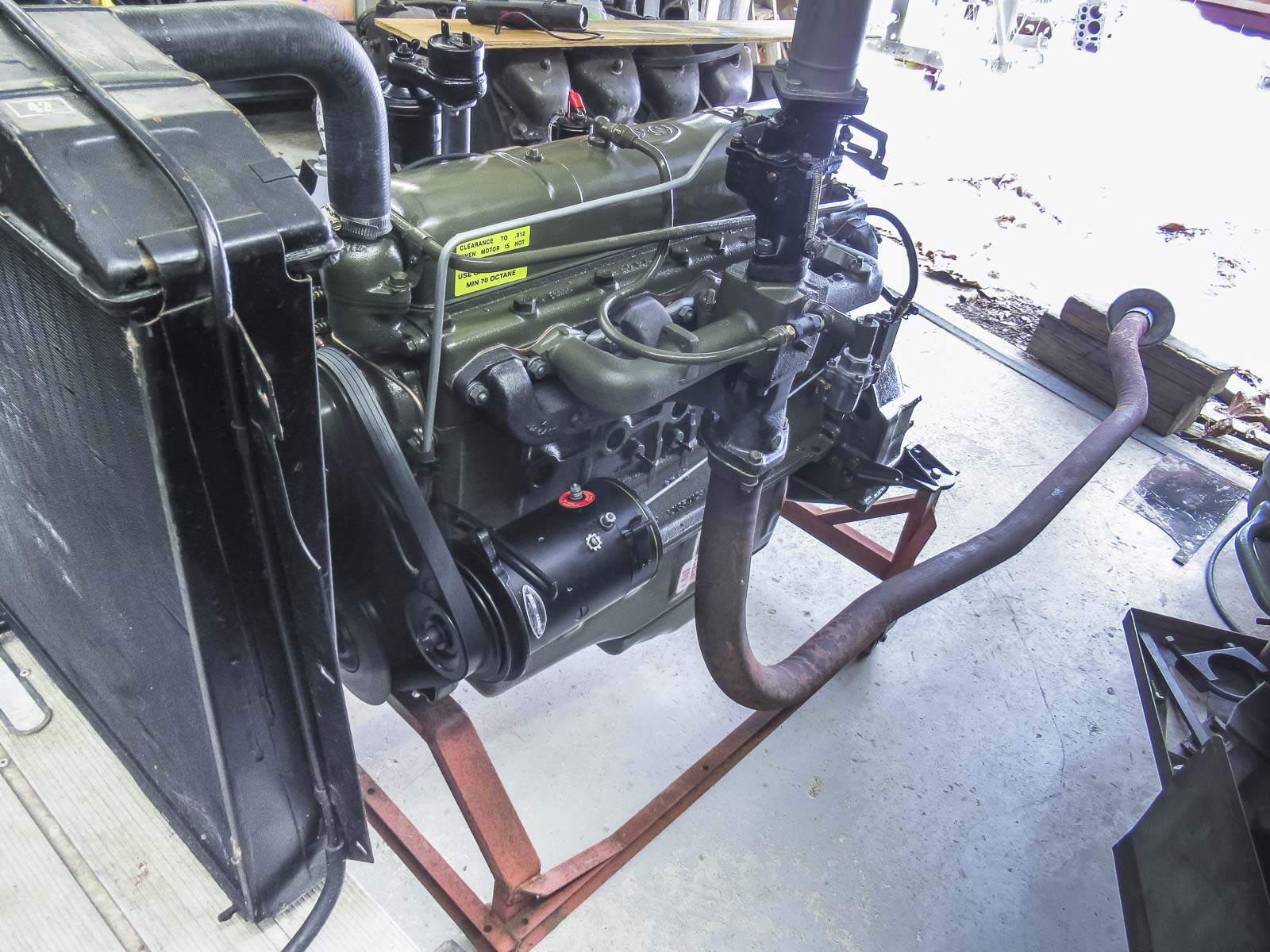
With the engine now fully assembled, it was time to verify its operability. To begin that process, the restoration team transferred the engine to a test stand and hooked up an extension to the exhaust manifold for channeling the combustion gases safely outdoors. While the initial attempt at an engine start revealed a problem, the restoration team resolved this quickly with the installation of a freshly-rebuilt distributor; a drive gear pin in the original unit had sheared.
Once the engine was running properly, the restoration team ran it for the requisite five hour test period. With the engine successfully returned to operating condition, next month should see the powerplant reinstalled in the truck!
