SBD Center Section Flap Bay :
The team at Pioneer Aero is preparing to begin their restoration of the wing center section. The first area which they will remove for rebuild is the flap bay, which attaches to the SBD’s rear spar. The following images describe this structure prior to its removal. Once the team detaches this structure, it will be fully disassembled, bead-blasted (or paint stripped) and inspected to determine each component's potential for future serviceability. Anything deemed reusable will be repaired, painted in primer and then then put safely into storage until required for refitting. Those items which are beyond salvage will be replaced, either with newly-manufactured parts or from identical original components sourced elsewhere.
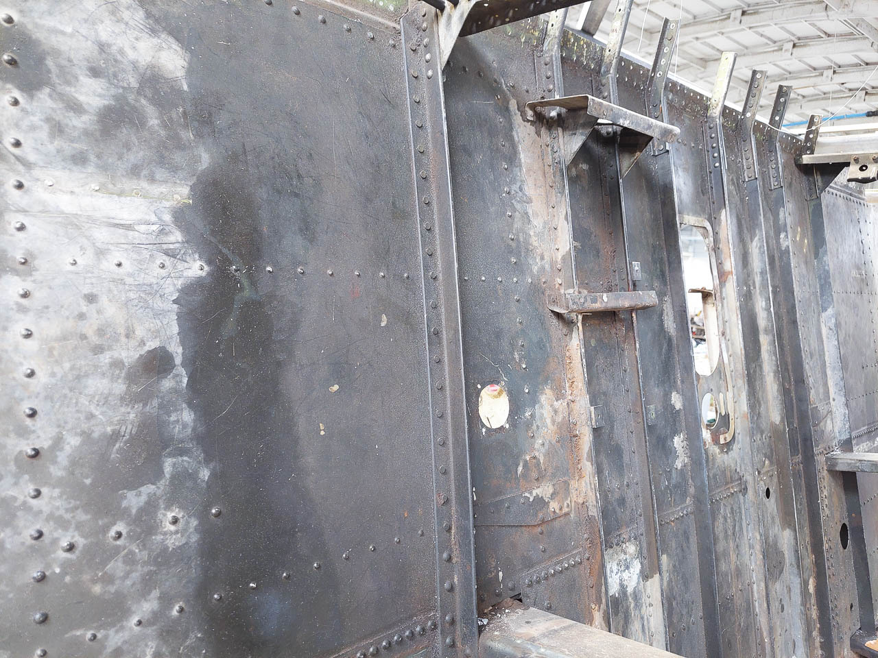
The flap bay prior to its removal as seen from the top side of the wing. This is the first area of the wing center section which will be removed and restored. The angle section running from top to bottom at the center of the image is where the fuselage skin meets the wing. The row of stringers beyond it are under the gunner’s floor in the aft cockpit. (image via Pioneer Aero Ltd.)
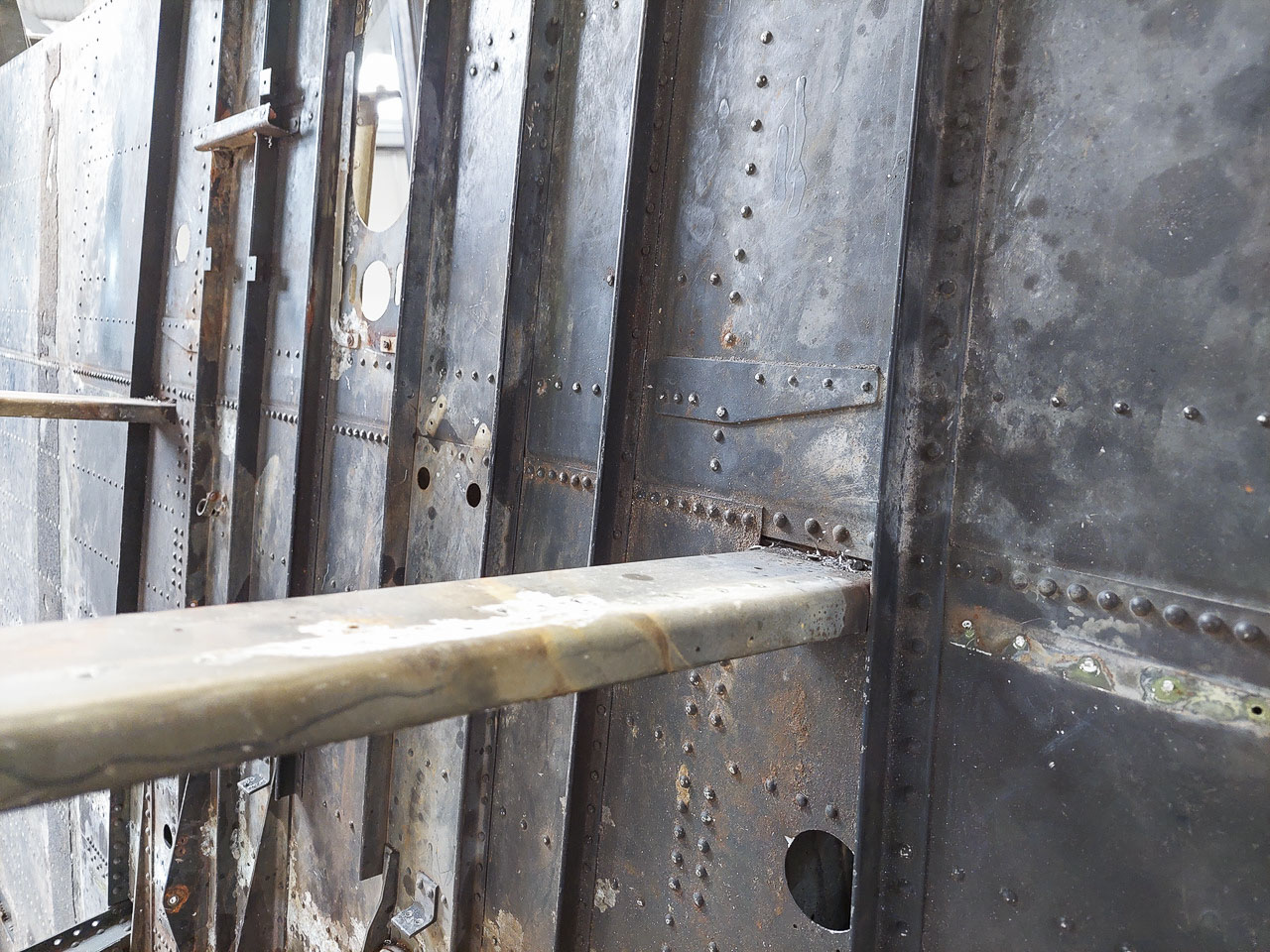
Another view of the flap bay from the top side of the wing center section, showing some of the under-floor fuselage stringers running from top to bottom. The structures protruding prominently from the top surface of the wing are fuselage frames, riveted to the rear spar beneath. (image via Pioneer Aero Ltd.)
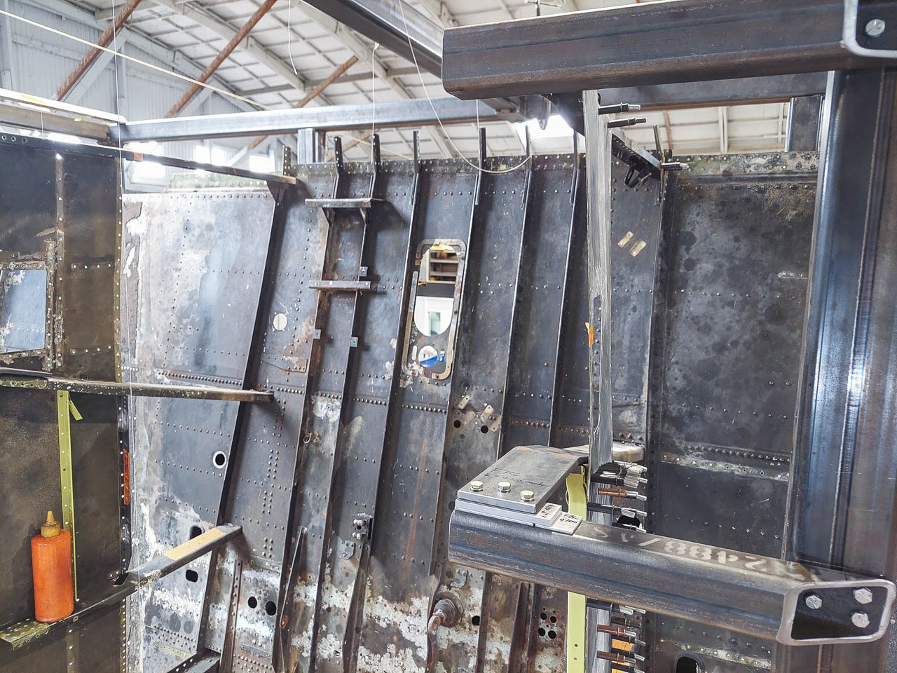
A further view of the flap bay prior to its removal, as seen from the top surface of the wing center section, but this time from further away to show some of the remaining structure lying atop it, or protruding from within. Some of the fuselage skins are visible to the left of the image, clecoed back in place on the fuselage frames. The steel structure at image right is part of the jig which Pioneer Aero Ltd has built to hold the wing and fuselage frames in their correct positions during SBD’s restoration. (image via Pioneer Aero Ltd.)
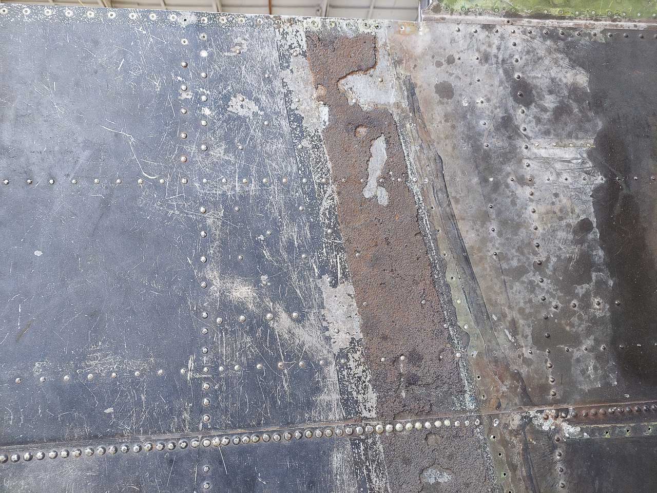
The top surface, center section wing skin over the flap bay. Running down the center of the image, you can see vestigial traces of the non-slip walkway material. Just to its right is where the wing root fairings were riveted to the wing skins. (image via Pioneer Aero Ltd.)
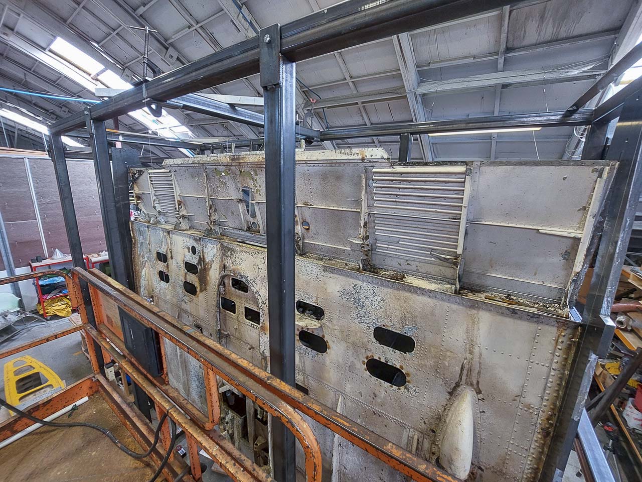
A closeup of the flap bay prior to its removal. Visible in this image are the lower surface of the wing, the aft face of the rear spar and the inside of the flap bay itself. The corrugated section on the right provides extra structural stiffness for the wing walkway area (lying on its reverse side) shown in the previous image. The structure at left is where the hydraulic ram for the flaps would normally be mounted (at wing center). (image via Pioneer Aero Ltd.)
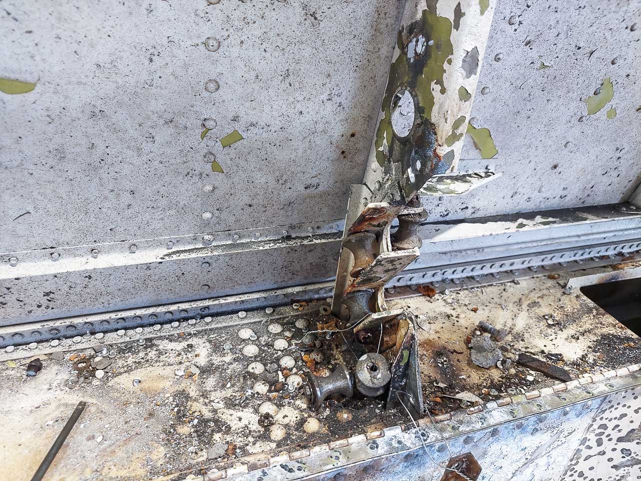
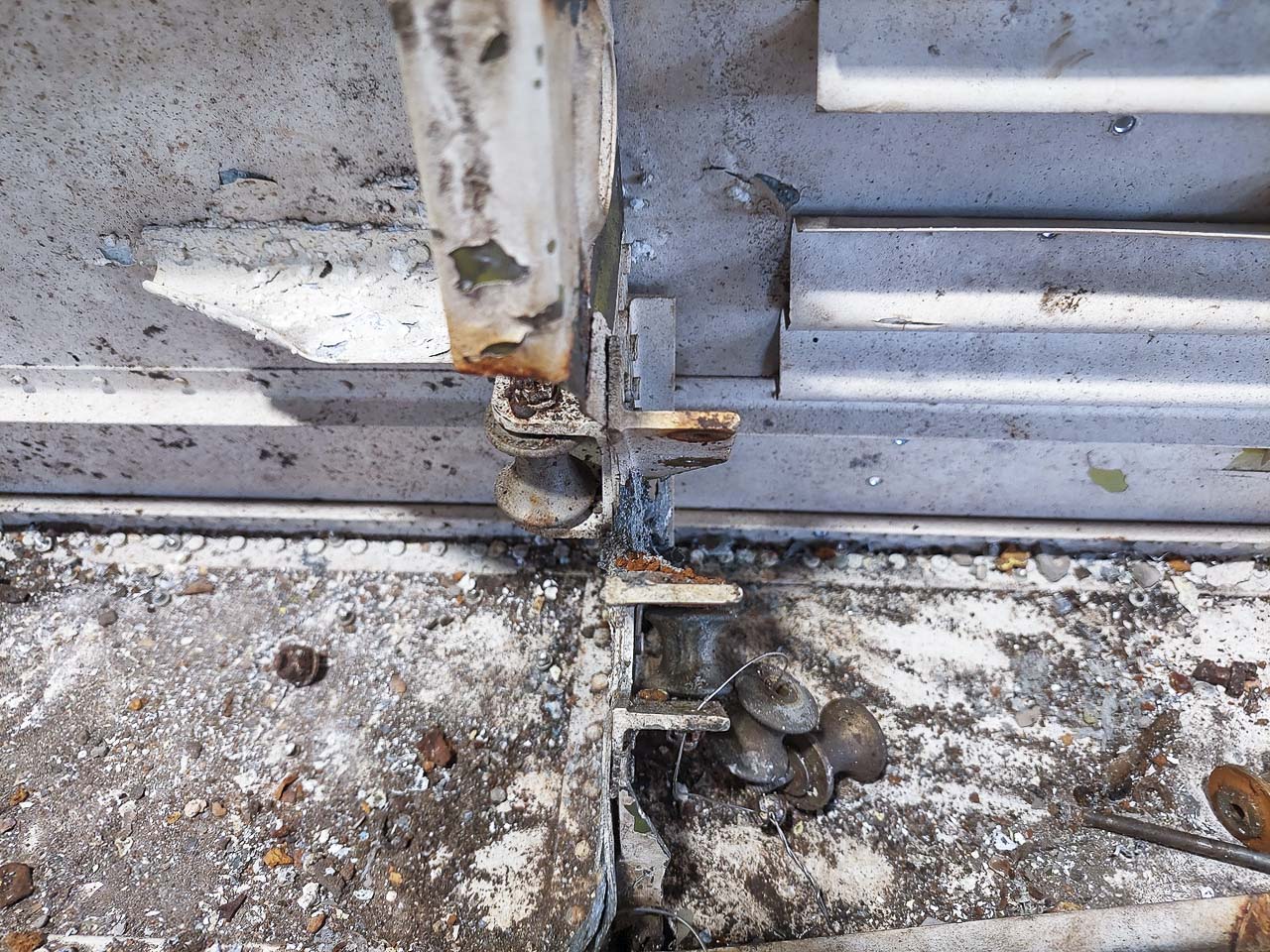
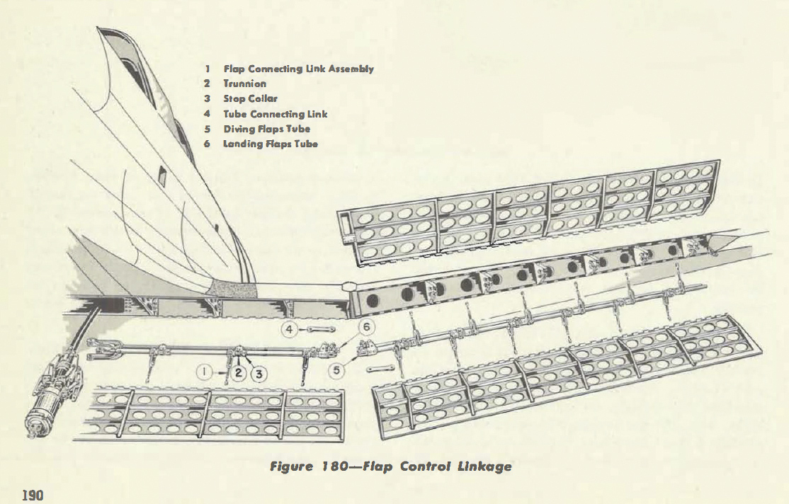
Visible in this image is the aft face of the rear spar and the inside of the flap bay. This is a close up of one of the flap roller mounts which allow the flap tube to move sideways during flap operations. The rollers themselves were removed when the flap tubes were removed (some time ago). (image via Pioneer Aero Ltd.)
A close up of one of the roller mounts which allow the flap tube to slip sideways during flap operations. Some of the rollers, removed some time ago, can be seen safety-wired together for safe keeping at the center bottom of the image. Also visible is an area of significant intergranular corrosion in the middle of the right side mount. Intergranular corrosion is an insidious kind of corrosion which forms along the crystalline boundaries in the aluminum alloy. It is not uncommon for WWII-era aluminum alloy extrusions to suffer from this kind of damage. In its severest form, it essentially turns the aluminum into the consistency of Weetabix breakfast cereal. Several of the flap roller mounts show signs of intergranular corrosion and will therefore need replacing. (image via Pioneer Aero Ltd.)
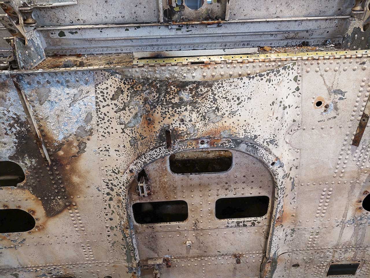
A view of the lower surface of the wing. The section of piano hinge running along the rear spar cap is where the center flap section attaches to the wing center section. The hydraulic flap ram is mounts to the structure at the top center of the image. The keel fairing is visible here; it is the large curved structure running down the middle of the image, and lies at wing center. (image via Pioneer Aero Ltd.)

