
Fuselage Disassembly:
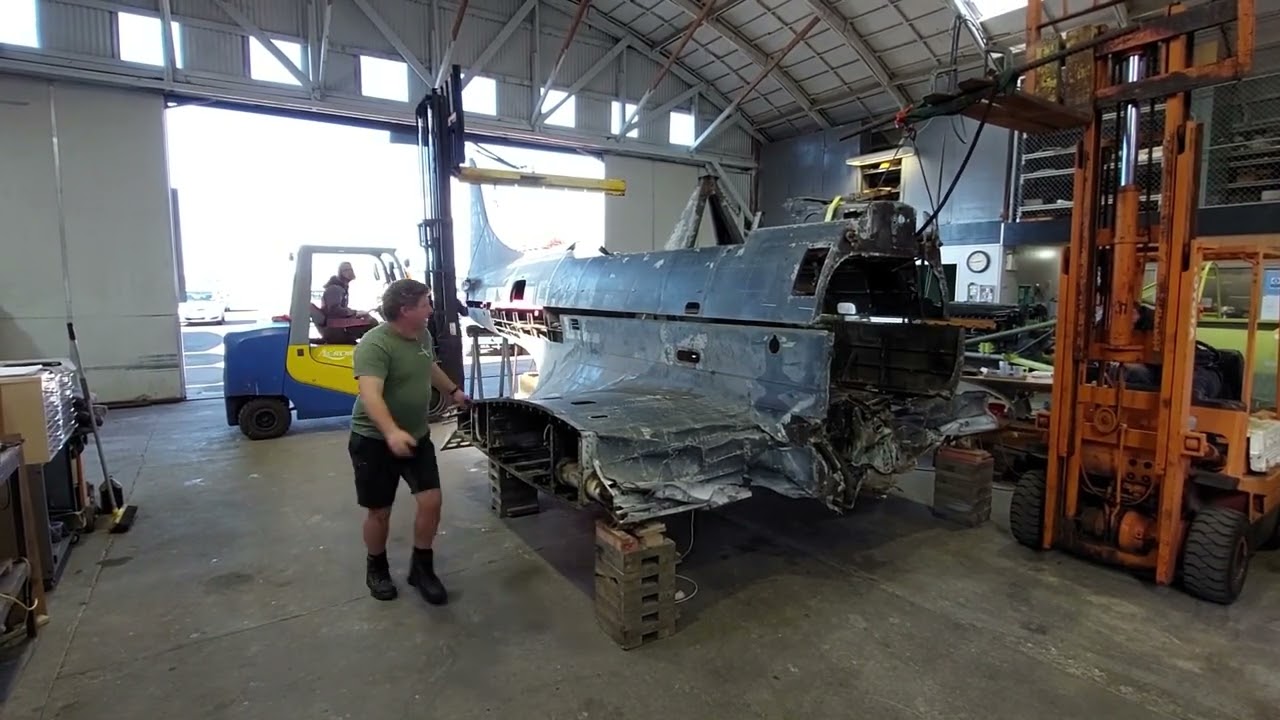
Over the past few weeks, the aircraft restoration specialists at Pioneer Aero Ltd. in Ardmore, New Zealand have begun the time-consuming process of disassembling the SBD’s fuselage into its major subassemblies. This will allow easier access to each of these components for a thorough, down-to-the-last-rivet rebuild.

Dauntless Fuselage - A Description:
Douglas designed the Dauntless around a semi-monocoque fuselage, meaning that the stressed-skin outer shell, which bears much of the loading, is reinforced with longerons and stringers. This is in addition to the ribs/frames and bulkheads usually found in a pure monocoque structure.
There are 17 frames in the SBD’s fuselage, running down its length at roughly 18” intervals, with Frame #1 being at the firewall while Frame #17 is where the tail gear attaches. The fuselage itself is divided into an upper and lower half, with the split occurring at the aircraft’s horizontal centerline. Each fuselage frame (except #17) has an upper and a lower half, riveted together with splice plates on either side of it. The skin panels for the upper and lower half are riveted along the #6 longerons on either side of the fuselage
The wing center section, while integral to the fuselage, is manufactured as a separate subassembly. The vertical stabilizer separates from the fuselage upper half at Frame #15.


The Breakdown Process:
To break down the fuselage into its major subassemblies, Pioneer’s engineers first removed what remained of the aircraft’s firewall at Frame #1. This allowed easier access to the interior of the forward fuselage. They then identified the various brackets, splice plates and stiffeners which needed removing to allow the separation of the upper half of the fuselage. The captions for the images below will explain the process in greater detail.


The SBD’s frontmost bulkhead frame (Frame 1) following the firewall’s removal. The structural supports for the firewall and ammunition cans were the next components to be removed. The left hand ammunition can (see top right) was pinched in place by some of the surrounding structure distorted in the crash and could not be extracted until the latter item was de-riveted. (photo via Pioneer Aero Ltd.)

Douglas SBD assembly drawing for the upper half of fuselage Frame #1. Note the two U-shaped cutouts for where the forward-firing machine guns will sit.
 Assembly Drawing")
A Douglas Aircraft assembly drawing for the lower half of Frame #1 for the SBD. Our Museum's Dauntless took a lot of impact damage at this location, with much of the structure either bent, torn or missing.

The aft face of the firewall following its removal; significant corrosion damage to this structure is clearly evident. (photo via Pioneer Aero Ltd.)

A view through Frame 1 into the pilot’s cockpit (following the firewall’s removal). The mount for the hydraulic tank is the closest item we can see on the left side of the image, while the throttle quadrant mount is the nearest in view on the righthand side. The large arrestor hook handle is visible, mounted to the cockpit’s rear bulkhead. The red hoop in the middle of the image is the locking mechanism for the pilot’s control stick. The upper and lower halves of the fuselage meet along the stringer which runs along the top side of the hydraulic tank and throttle mounts. (photo via Pioneer Aero Ltd.)

A view of the front side of the righthand joiner structure at Frame 3. The two heavy-gauge angle extrusions riveted between the Frame and the skin are still in place at this point. They needed removing to permit the separation of the upper and lower halves of the frame. This is the strongest fuselage joint on the entire airframe. (photo via Pioneer Aero Ltd.)

The aft side of the joiner structure at Frame 3 is the main focus of this image. The heavy-gauge sheet metal plate (with 44 neatly-spaced rivets) helps hold the upper and lower halves of the frame together. It will be de-riveted and removed in the same fashion as the now-absent joiner plate at Frame 2. (photo via Pioneer Aero Ltd.)

The aft side of the righthand joiner structure at Frame 3 following the removal of the rivet heads holding the joiner plate to the structure. De-riveting requires a lot of skill for such heavy-gauge rivets, since their material hardness is often significantly greater than for narrower gauge examples. In all cases, they must be removed without damaging the mounting holes or surrounding structure. It is easy for a drill bit to skip off hardened rivets during the removal process, so great care is required. The next step is to drill out the remaining rivets to begin the process of removing the angles on the front side of the frame. (photo via Pioneer Aero Ltd.)

The resulting ‘swarf’ gathered on the compartment floor following lots of drilling to remove each of the required items in the aft righthand corner of the pilot’s cockpit. (photo via Pioneer Aero Ltd.)

A later view into the pilot’s cockpit through Frame 1. This is following the removal of each of the components binding the upper and lower fuselage halves together. These items included stringers, frame joiners and the diaphragm joiner. A lifting sling is already in place, attached to the upper engine mounts. (photo via Pioneer Aero Ltd.)

The forward righthand corner of the gunner’s cockpit showing various mounting shelves and brackets still in place. These items needed de-riveting to permit fuselage separation. (photo via Pioneer Aero Ltd.)

A later view of the front righthand corner of the gunner’s cockpit, which is now ready for the fuselage split to occur. Note the absence of the key mounting brackets, frame joiners and stringers seen in the previous image. (photo via Pioneer Aero Ltd.)

The aft end of the gunner’s cockpit prior to the removal of the components binding the upper and lower fuselage sections together. The ammunition can for the aft gun, foot steps (front lower corners) and various mounting brackets still needed removing at the time this image was captured. (photo via Pioneer Aero Ltd.)

The aft end of the gunner’s cockpit ready for the fuselage split. Note the absence of those key components mentioned in the previous image. (photo via Pioneer Aero Ltd.)
SBD Walkaround with Martin Hedley


This image shows the fuselage right before Pioneer Aero lifted off its upper half. (photo via Pioneer Aero Ltd.)

Another view of the fuselage just prior to lifting away the upper half, this time from the rear. (photo via Pioneer Aero Ltd.)
Fuselage Separation Timelapse Video
Next Steps:
Pioneer Aero’s engineers are currently building jigs to hold the wing centre section and upper fuselage to permit their accurate restoration. The next step will involve separating the rear sections of the lower fuselage, which split off just aft of the wing trailing edge. The radio rack, aft diaphragm in the pilot’s cockpit, and floor structure in the gunner’s cockpit will also have to come out. The team will then de-rivet the wing root fairings and remaining fuselage on the topside of the wing center section. The vertical stabilizer assembly will also be separated from the upper fuselage and placed in a jig for restoration.
The team plans to focus their restoration efforts on the wing center section and upper fuselage simultaneously. Once the wing center section is done, they will rebuild the lower fuselage section which mounts atop it. And when they have completed the upper fuselage section they will proceed to the lower aft sections. There is still a lot of work to do, but it is clearly full speed ahead in Ardmore! We look forwards to revealing the latest work from the master craftsmen at Pioneer Aero Ltd.

The upper fuselage following its removal from the airframe. The next step for this assembly will involve detaching the vertical stabilizer. After that, the remainder will go into a jig for restoration. (photo via Pioneer Aero Ltd.)

A diagram showing the various components of the SBD's empennage. The vertical stabilizer subassembly is clearly identifiable, and should give readers an idea of where Pioneer Aero will separate it from the upper fuselage. (image from p.80 of SBD Erection & Maintenance Manual)

The lower half of the SBD’s fuselage following the removal of the upper half. The next step will involve detaching the aft portion of this section, which separates just behind the wing trailing edge. (photo via Pioneer Aero Ltd.)
 P59 E&m Small")
A factory-fresh view of the SBD wing center section top side as pictured on Page 59 of the Dauntless Erection & Maintenance Manual. This should provide an idea of what the team a Pioneer Aero is aiming for with the rebuild of the Museum's SBD-5.
 P59 E&m Small")
Sbd Wing Center Section (bottom View) P59 E&m Small