Refurbish or Replace?
Pioneer Aero had to remove numerous small parts in order to separate the SBD's fuselage into its major subassemblies. While some members of the restoration team are focused on the larger assemblies, others have begun assessing the smaller items, refurbishing what is rebuildable and remanufacturing what is not.
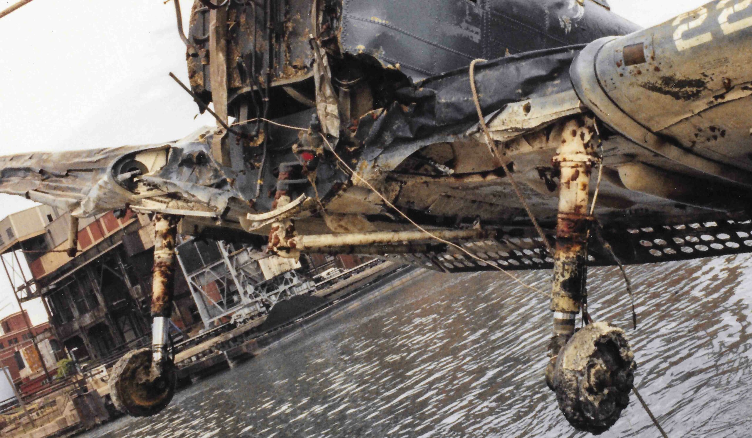
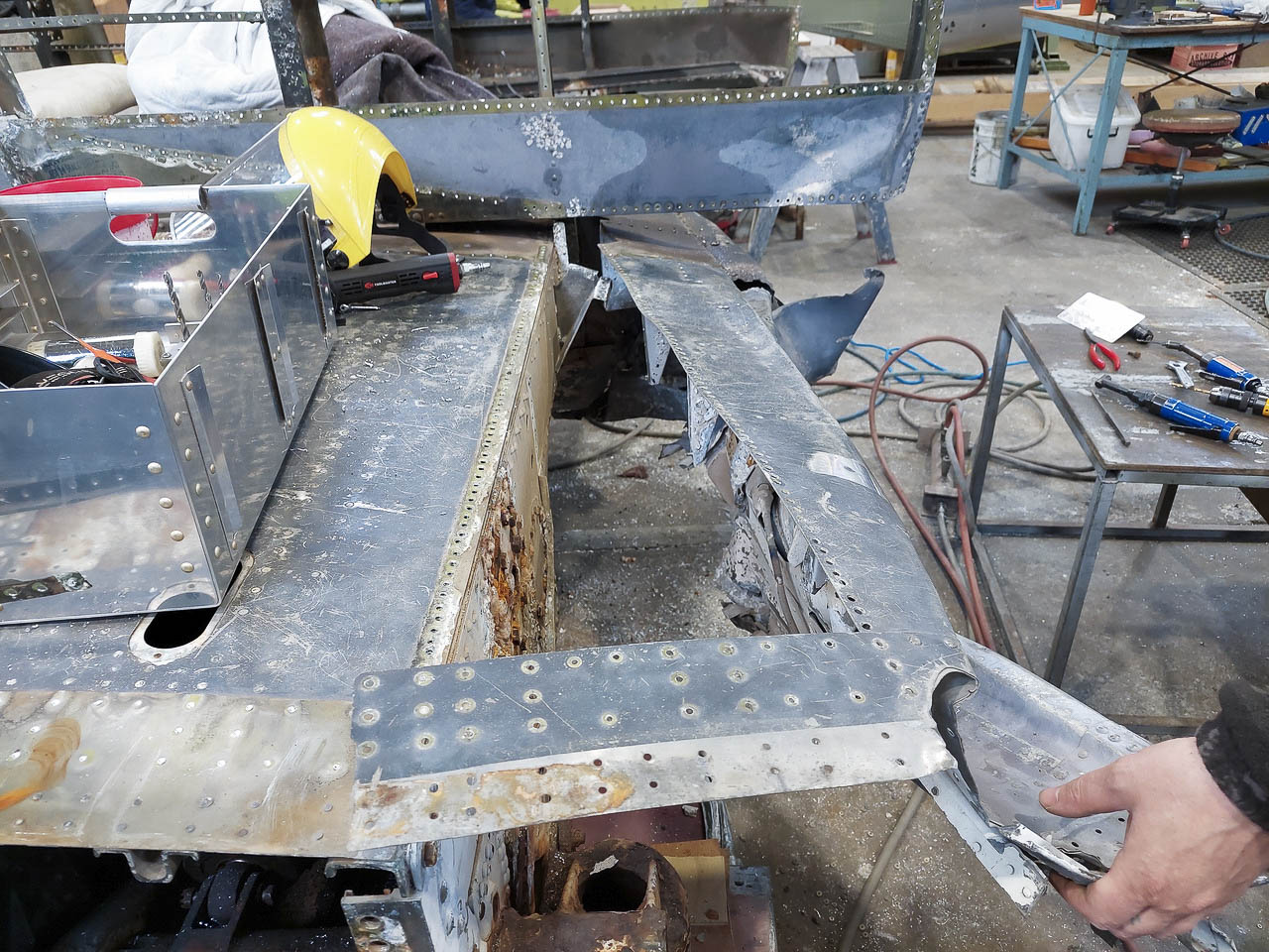
There is an old adage in aircraft restoration which seems to prove true all too frequently: "If it ain't bent it's corroded, and if it ain't corroded, it's bent." Even so, it is often possible to save and refurbish damaged components, as the Pioneer team has demonstrated time and again on this project. The SBD's wing leading edges have proved a particular challenge, however, as the above image intimates...
Crash Damage:
When our Dauntless ditched into Lake Michigan in January, 1944, the dive bomber's forward fuselage and wing leading edge took a pummeling as they struck the water. Indeed, the crash essentially crushed the wing's leading edge flat against the main spar in places. A couple of months ago, the restoration team carefully stripped back this structure on the wing's center section (see image above) as part of their preparations for separating the fuselage. More recently, they began disassembling this crumpled mass of metal to assess what remained, and began replicating the parts which proved beyond salvage.

Wing Leading Edge Structure:
The SBD's center section wing leading edge structure comprises many different subassemblies, as revealed in the image above from page 50 in the A-24 illustrated parts manual. The elements labeled #23 and #24 in the drawing are of particular interest in this update. These components are officially described as "Web Assembly - Center Section Wing Nose", with the left hand example having part number 5062769, while the right is 5062769-1. While these numbers may seem innocuous to many, Douglas Aircraft employed a useful logic in their parts numbering protocol, which is worth examining further.

The Douglas Aircraft Company Part Numbering System:
To keep track of where everything goes, each of the many thousands of parts involved in the manufacture of an aircraft requires its own unique identifier - typically a number.
Different manufacturers each had their own methodology for part number assignment, but the Douglas Aircraft Company came up with a particularly effective one. While they too labeled each subassembly with a seemingly random number, Douglas reused this number as the basis for identifying the individual parts comprising that component, simply adding a hyphenated numerical suffix (e.g. "-23") to differentiate them from each other.
Furthermore, since aircraft are usually symmetrical, they have numerous, near-identical parts which are essentially mirror images of each other - oriented in either a right- or left-handed configuration. To simplify the process for the factory workers, parts with a righthand orientation had an odd-numbered suffix, while those on the left were even-numbered. This made it much easier for them to be certain they were working with the correct parts when fabricating a given subassembly.

Drawing Information Block - An Explanation:
The above image is a close up of the Information Block from the earlier drawing for Douglas part #5062769, the web assembly for the SBD center section’s wing leading edge. While this image is fuzzy, and perhaps a little confusing to those who aren’t used to reading manufacturing drawings, there are essentially four important areas of information depicted here.
- The block at the lower right delineates what the drawing describes, along with the names of the people who created and/or updated the drawing, as well as the dates of each release.
- The block at the lower left delineates the “change notices” in this version of the drawing, what they involved, who signed off on them, and when.
- In between these blocks at the bottom of the image, is another identifying the next assembly associated with the component this drawing describes, and the particular aircraft variant it involves.
- Perhaps the most important information, however, is featured in the “bill of materials” table at the top right. Reading from the left, the first two columns identify the part number suffix; odd numbers being for the right-handed components and the even for the left. The third column describes how many of that given part are needed. Adjacent to these three columns is information describing the material these parts are made from. This particular assembly primarily comprises parts made from either aluminum sheet stock or extruded aluminum. For the extruded parts, the bill of materials essentially identifies which extrusion profile to use, its length, material and temper state. However, for the parts made from sheet metal, there are a series of squares identifying the length and width of the material blank to start forming the part from, the thickness, alloy and tempered state of this material before manufacture commences, and then the material specifications the part must conform to following its completion.
Web Assembly - Center Section Wing Nose:
Douglas Part Number 5062769 essentially serves as a secondary spar, connecting ribs between the main spar and leading edge, while stiffening the structure over the wheel bays. As typical for its era, this component consists of a flat, sheet metal assembly (the web) with stiffeners (spar caps) running down its lateral extremities. Understandably, given how comprehensively the water impact crushed this area of the aircraft, very little of the original structure was salvageable, but what remained has served as a useful template (complemented by original factory drawings) for the remanufacture of replacement parts.
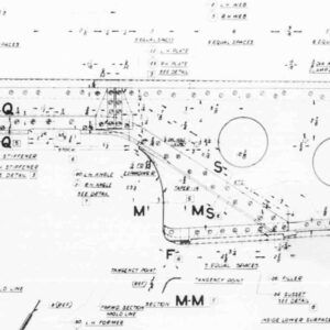
The following images describe some of the work underway to rebuild the web assembly. We have included closeup views of the earlier manufacturing drawing for Part Number 5062769, highlighting where each of these different components fit in the overall subassembly. Hopefully this provides a clearer idea of the work which the restoration team is undertaking, and how much effort is involved!
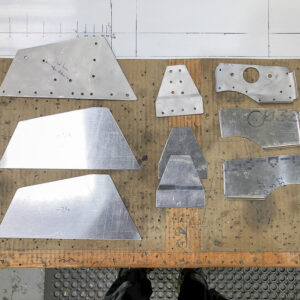
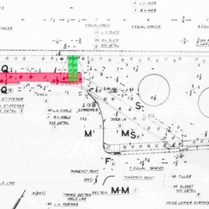
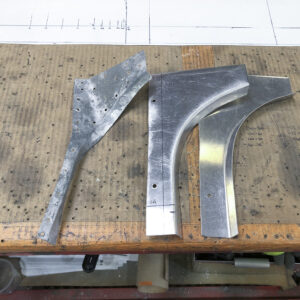
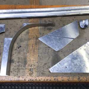
Some of the smaller components for the nose spar web assembly are pictured here, alongside their newly-manufactured replacements (for both the left and righthand assemblies). The following image shows where these pieces attach to the web structure itself. (photo via Pioneer Aero Ltd.)
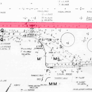
A close up of the nose spar web assembly drawing. The red-tinted sections highlight the locations where the components in the previous image attach; part numbers 5062769-22(LH)/-23(RH), -24, and -16(LH)/-17(RH) as viewed from left to right.
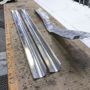
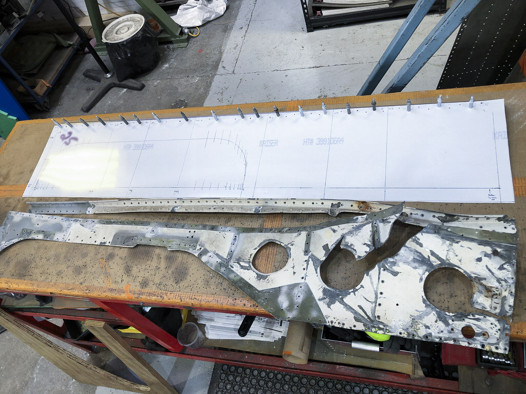
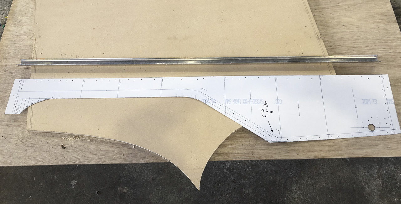
Partially remanufactured spar caps for the 5062769 web assembly alongside a badly mangled original. These components run along the top edge of the web assembly, as revealed in the following image from the manufacturing drawing. (photo via Pioneer Aero Ltd.)
The spar cap, highlighted in red is part number 5062769-7, which fits in the righthand version of the web assembly, and -6 for the lefthand side.
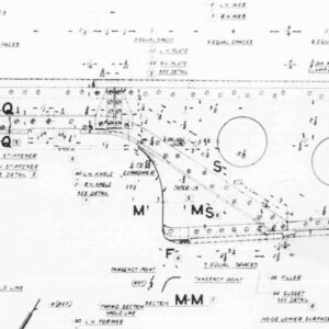
Some of the salvageable leading edge web assembly components following media blasting. These parts are highlighted in red (large) and green (small) within the following drawing. (photo via Pioneer Aero Ltd.)
Newly manufactured formers for the spar web alongside a very crumpled original. These parts,5062769-28(RH) and -29(LH) line the inside of the web and help define the inboard shape of the wheel well cut out - as highlighted in red within the succeeding image. Note that the new metal is only partially completed; it still requires trimming and mounting holes. These parts attach to the front side of the web assembly. (photo via Pioneer Aero Ltd.)
The web assembly, with Part #5062769-28 highlighted in red. The mirror image for the left hand web has a -29 part number.
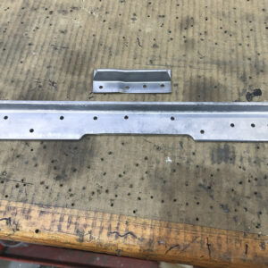
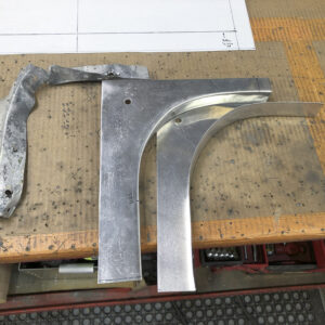
Newly manufactured formers for the spar web alongside a very crumpled original. These parts line the inside of the web and help define the outboard shape of the wheel well. These parts lie on the rear side of the web assembly. (photo via Pioneer Aero Ltd.)
Assembling the Web:
With parts for the secondary spar either refurbished or remanufactured, it was time to begin putting it all together.
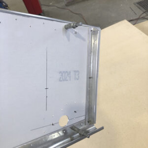
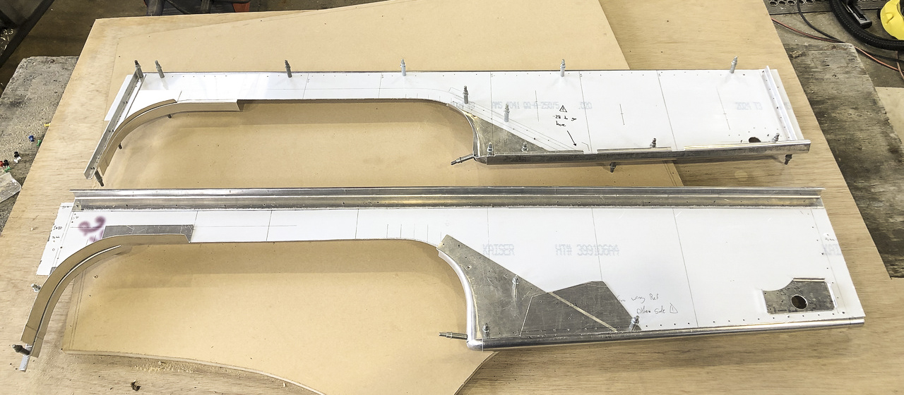
A selection of the refurbished and remanufactured web components ready for reassembly. (image via Pioneer Aero Ltd.)
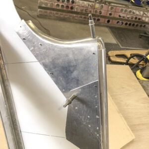
A close up of the components attached to the web at the inboard end of the nose spar. (image via Pioneer Aero Ltd.)
A close up of the components attached to the web at the inboard corner of the wheel well cutout in the nose spar. (image via Pioneer Aero Ltd.)
Leading Edge Ribs:
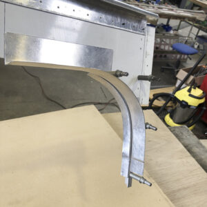
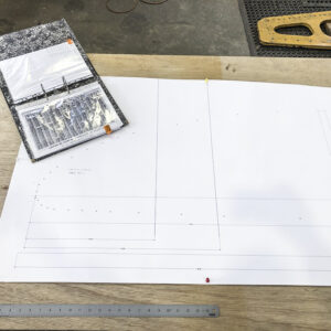
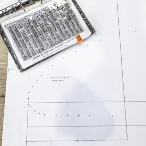
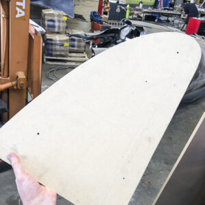
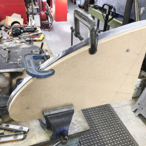
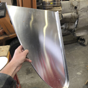
The remanufacture of all the leading edge ribs for the wing center section is also underway now. Using Douglas Aircraft's ordinate table drawing, which tabulates the coordinates defining the outer profile for each rib, the team cut out an appropriately sized forming block to shape a sheet metal blank into a new rib. Once fully formed, the rib is ready for heat treating to significantly increase the material's tensile strength and hardness.
While it is a little difficult to see, this image shows the drawing for the full-scale profile for one of the leading edge ribs, the ordinates (x & y positions) marked as crosses along the outer edge. (image via Pioneer Aero Ltd.)
A closeup of the drawing with the crosses marking the outer profile of a leading edge wing rib. The document in the upper left is the manufacturer's ordinate chart, tabulating the x & y coordinates which define the outer edge of each rib profile. (image via Pioneer Aero Ltd.)
The completed wooden former, ready for shaping the aluminum blank over its edges. (image via Pioneer Aero Ltd.)
A blank piece of aluminum alloy sheet metal is slowly being shaped around the edges of the forming block. (image via Pioneer Aero Ltd.)

Skin Assembly - Center Section Wing Nose:
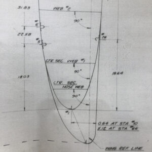
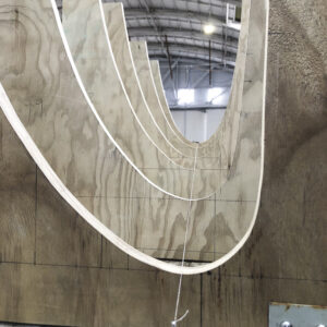
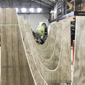
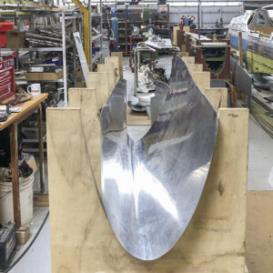
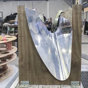
Douglas Part Numbers 5090535-2 and 5090535-3 form the skins for the leading edge in the SBD's wing center section; Pioneer Aero has begun forming these key parts in recent days. Using the manufacturing drawing below (amongst others) the restoration team was able to create a jig-like cradle defining the cross-sectional profile for these skins. Using a combination of a rolling machine and an English Wheel, the engineers shaped a section of sheetmetal so that it conformed to the cutouts in the jig, a tool which they amusingly refer to as 'dinosaur bones', for obvious reasons. Once the team has completed and assembled the internal structure for the wing leading edge, they will rework and trim the skin section so that it lines up perfectly on top.

Another of the drawings which Pioneer used to create the cutouts for the wing leading edge profile jig. The outer profile defines the wing leading edge cross section at Station #10, where the wing meets the fuselage, while the inner profile describes the leading edge cross section at wing Station #66, at the mating point with the outer wing panel. Another section of this drawing (not shown) contains tables outlining the curve ordinates for the nose ribs.(image via Pioneer Aero Ltd.)
Lining up the cutout sections for the 'dinosaur bones' jig defining the leading edge for the wing center section. The string running down the middle defines the wing center line. This particular jig is for the right wing, with the nearest cutout representing the rib at wing Station #10, and the furthest at Station #66. There is obviously quite a change in cross-sectional profile across this distance. (image via Pioneer Aero Ltd.)
Another shot during the effort to align the jig properly. Note the green laser trace at the upper left. (image via Pioneer Aero Ltd.)
The leading edge skin being trial-fitted into the dinosaur bones jig during the forming process to make sure its shape is heading in the right direction. (image via Pioneer Aero Ltd.)
The leading edge skin more or less fits perfectly into the dinosaur jig at this point. Note that there is a lot of spare material around its edges. Once the internal leading edge structure is completed and assembled, the skin will be final-fitted onto it to make sure it nests perfectly. Any excess material will then be trimmed away. (image via Pioneer Aero Ltd.)

