SBD Dive Flaps:
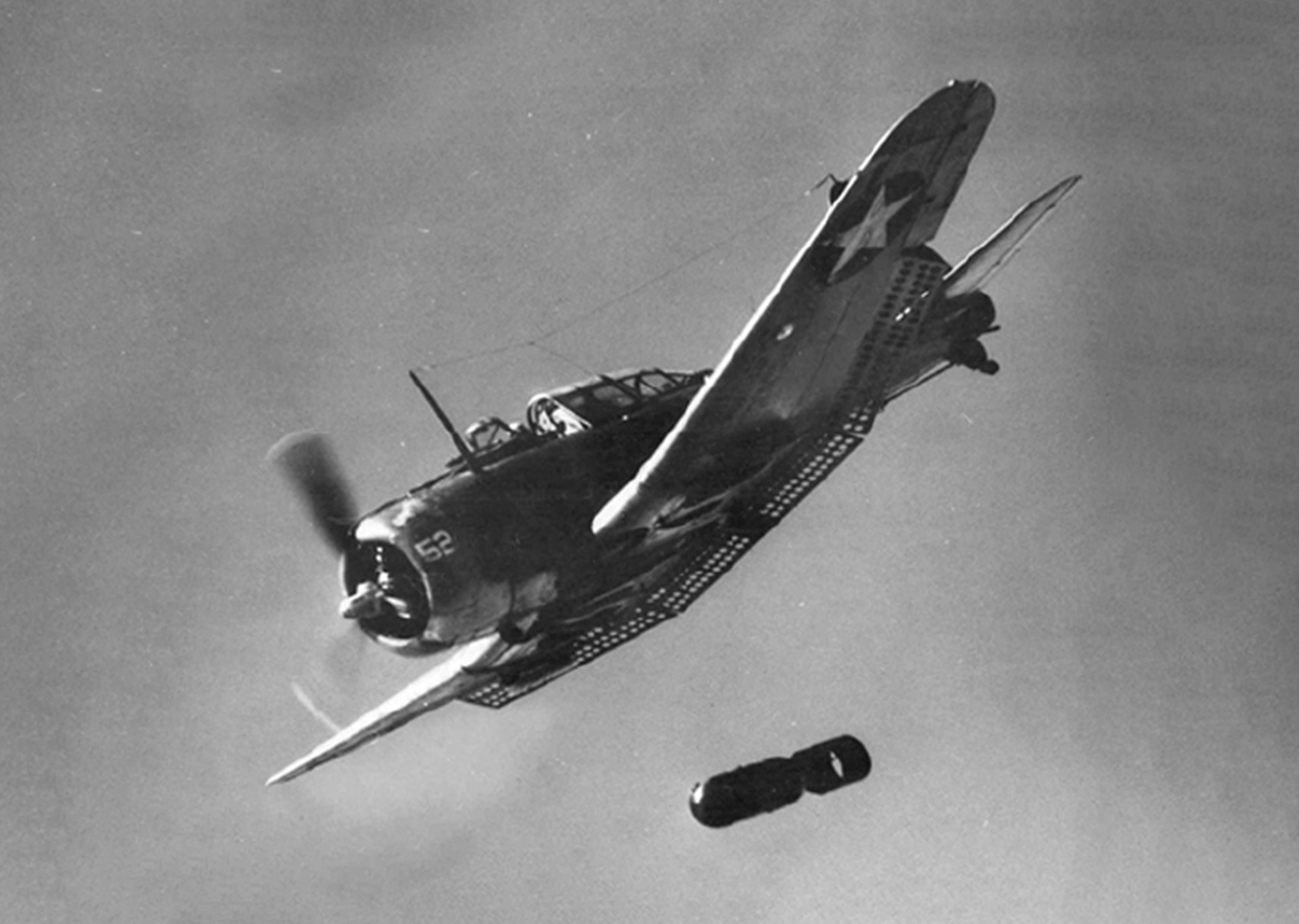
One of the SBD's defining features is its set of perforated flaps which runs along the entire wing trailing edge between each aileron. When fully deployed, these flaps were critical to the aircraft's success as a dive bomber. They regulated the aircraft's velocity while also providing greater stability in a dive, so the Dauntless pilot could make aiming adjustments more precisely to deliver their ordnance on target. Indeed, the type proved so effective in its role that it was Dauntless crews who executed the fatal blows for each of the four Imperial Japanese Navy aircraft carriers sunk during the Battle of Midway in June, 1942 - an engagement which turned the war in the Pacific inexorably in the Allies' favor.
Flap Configuration:
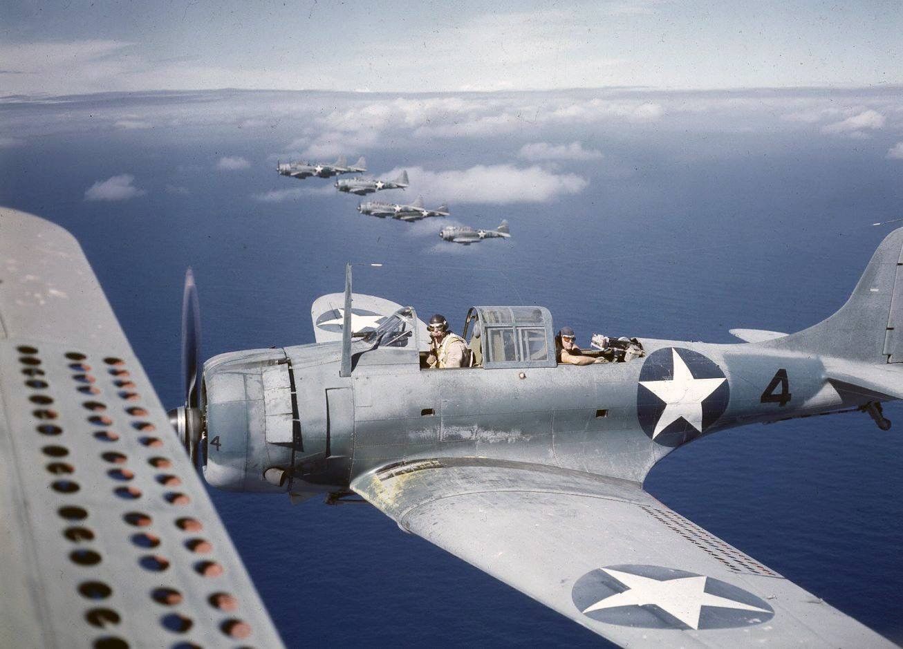
There are actually five major control surface components in an SBD's set of flaps. One flap lies beneath the wing center section, while each outer wing panel has a pair of perforated flaps laid one on top of the other. During normal take off and landing operations, only the lower units deploy (as conventional flaps). However, during a bombing run, the SBD's pilot will actuate the upper flap panels on the outer wings as well.
Rebuilding the Center Flap:
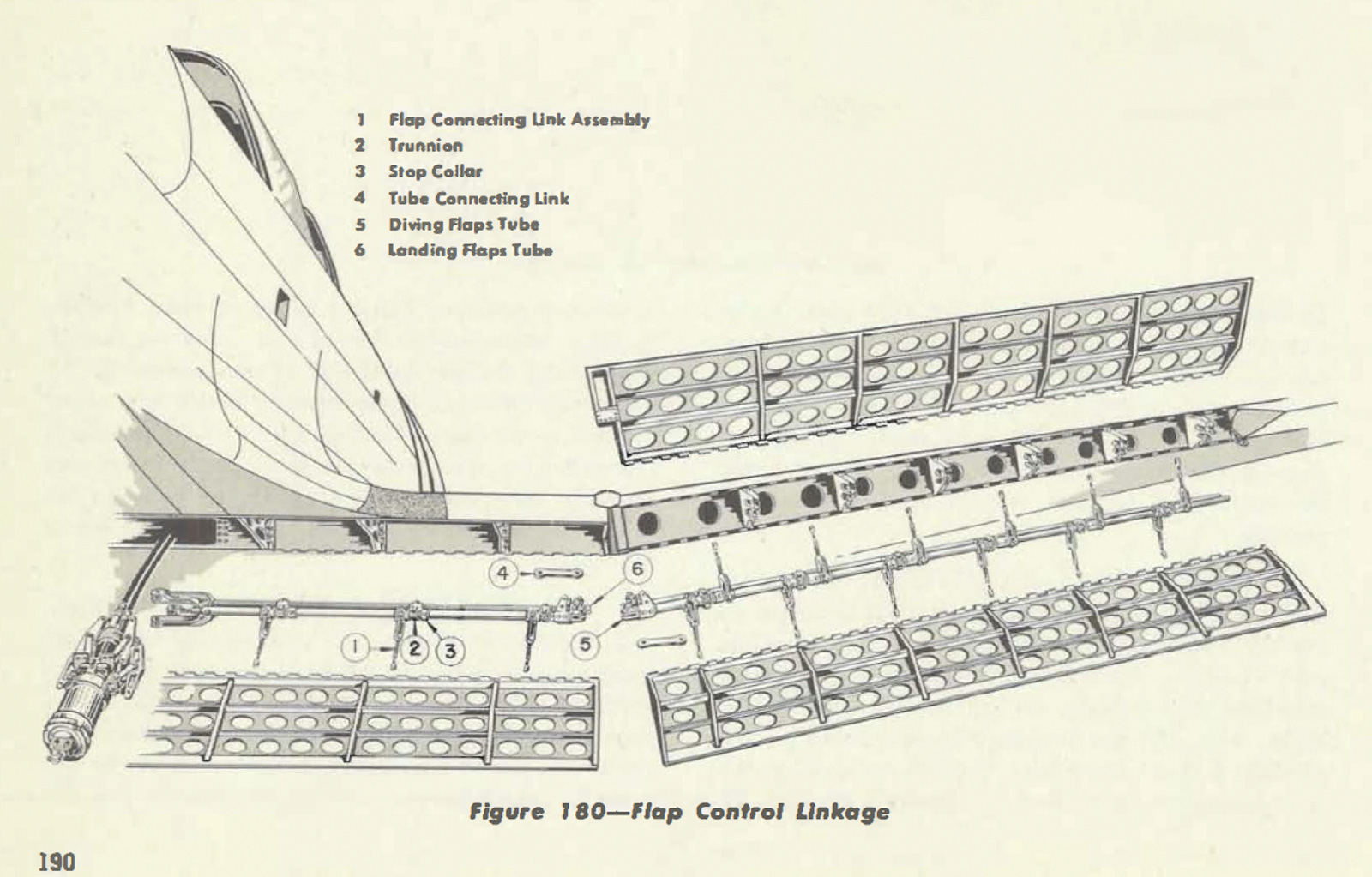
Over the last few months, the team at Pioneer Aero has begun rebuilding the central flap panel for the Museum's Dauntless. This panel is substantial in size, extending the entire eleven foot width of the SBD's wing center section. While BuNo.36175 was recovered with its set of flaps, the center unit was too badly damaged for reuse unfortunately.
Thankfully, a donor unit was available. Although this too has significant serviceability issues, some of its key components are reusable. The restoration team began the rebuild process by fully disassembling the flap and then assessing each component for its potential future airworthiness.
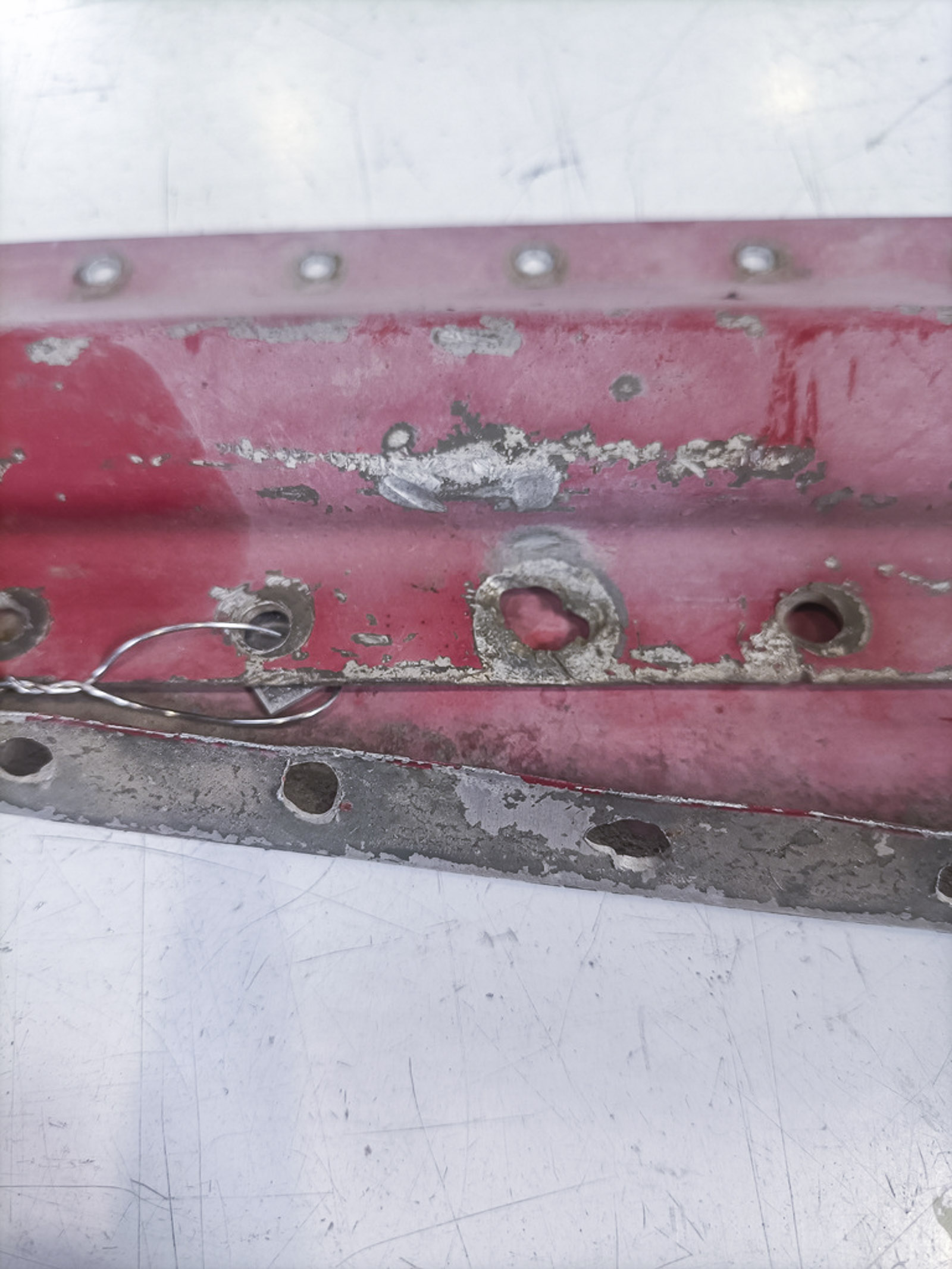
Pioneer's engineer, Jayden Malloy bead-blasted each of the parts he deemed salvageable to clean away any paint, dirt and minor corrosion. Once cleaned, however, a number of these pieces revealed substantive cracks and/or oversized rivet holes - damage too severe to effect airworthy repairs.
Leading Edge Channel Sections:
Upon his initial inspection, Jayden felt that the flap's original leading edge channel sections appeared to be in decent condition, with only minor, repairable dents to contend with. Upon closer inspection, however, all but three of these components featured enlarged rivet holes, rendering them unusable. Thankfully, these parts are not overly complex to remanufacture - for those with the requisite skills, that is.
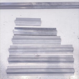
Each channel section is formed from a piece of flat aluminum, with a specific cross-sectional profile folded into it using a sheet metal brake. Jayden decided that it made sense to create a small production run of these channel sections, rather than build them piecemeal. Even with the correct dimensions from manufacturer's drawings and the reference parts on hand, Jayden still needed to determine the correct method for folding the new aluminum sheet into the correct profile. A trial run using a piece of scrap aluminum sheet showed that he needed to adjust his setup slightly, so he tried again. The third trial yielded the perfect profile.
With this information in hand, Jayden noted: "I cut my six final pieces to size, inked my four fold-lines on each of them, and folded them - all in one hit - knowing they were going to come out within dimension!"
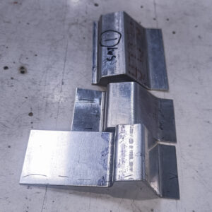
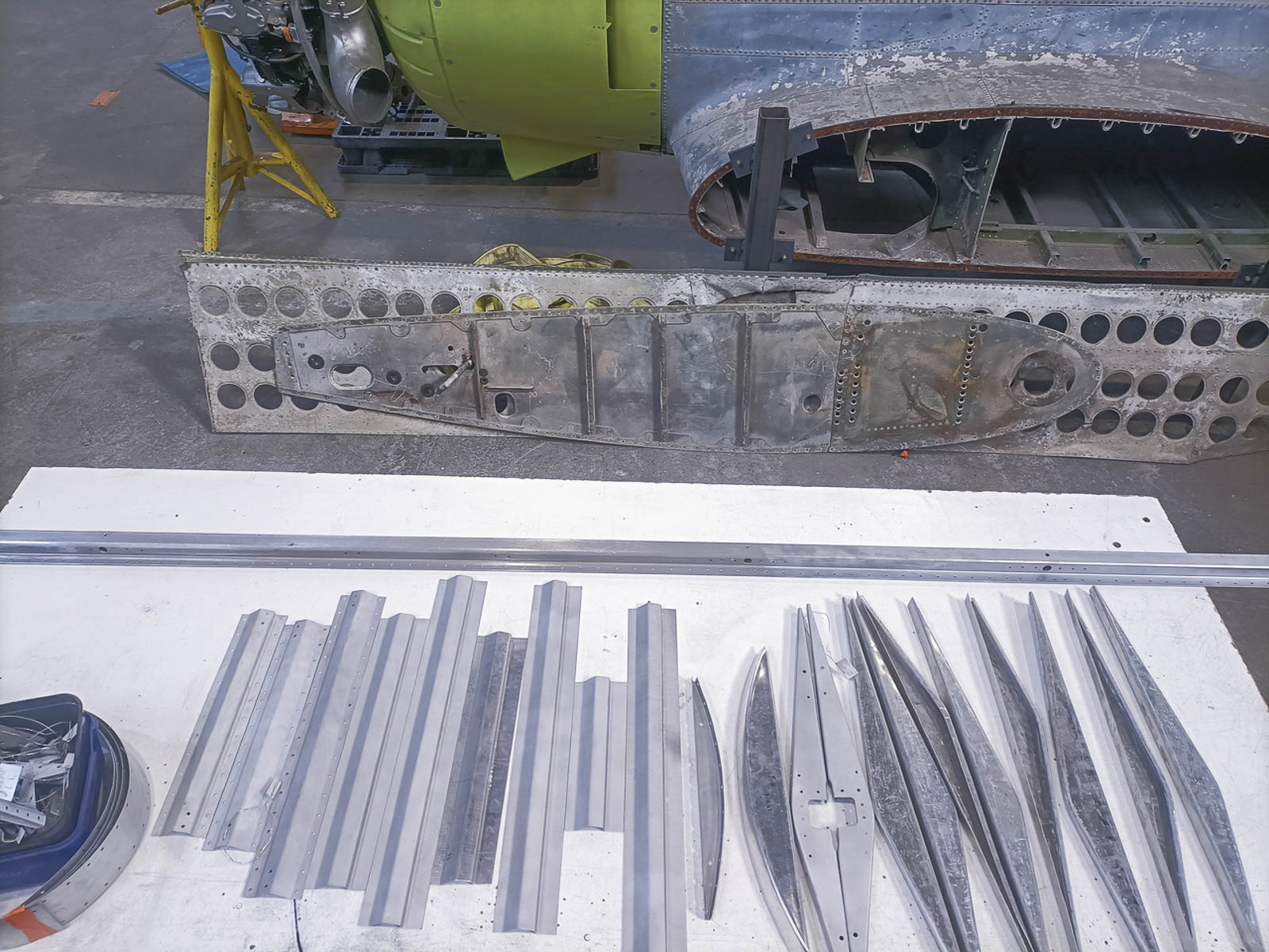
Thankfully, most of the brackets and doublers on the center flap proved to be in good condition, and required minimal panel beating to regain their proper shape. Having these original parts - with their rivet holes as guides - makes it easier to put the flap back together since the holes will help align new material with old.
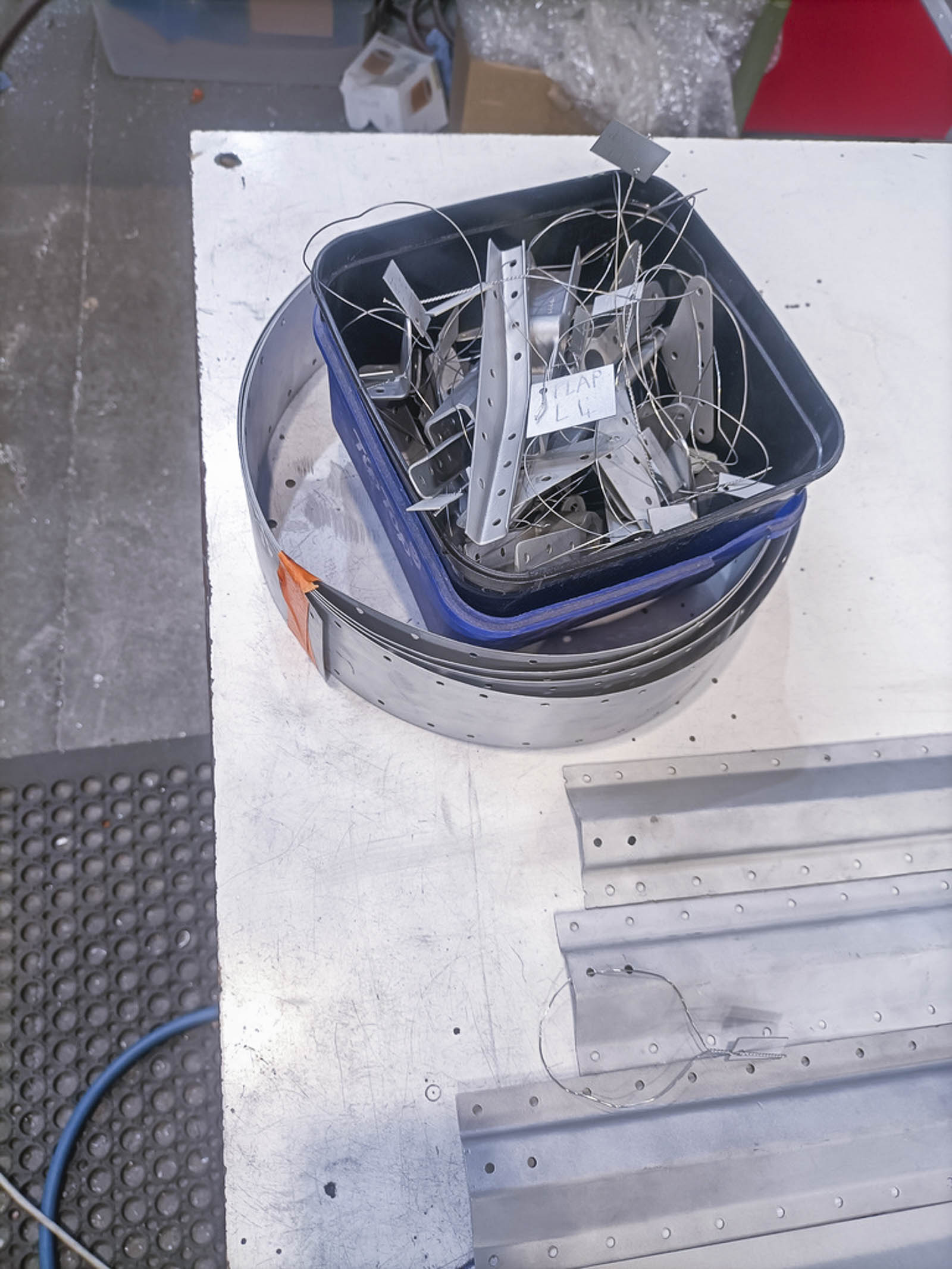
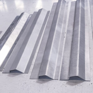
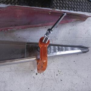
These are the three trial pieces which Jayden used to determine the method for forming the correct cross-sectional profile of the new leading edge channel sections. (image via Pioneer Aero Ltd.)
Remanufacturing Dive Flap Ribs:
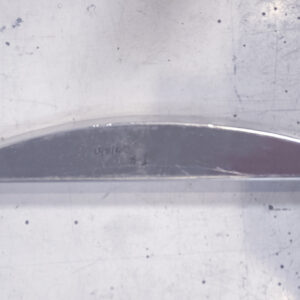
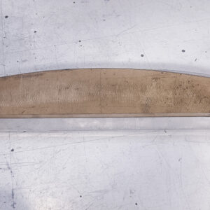
Some of the ribs which stiffen the central dive flap structure were too damaged to save, so Pioneer Aero's Jayden Malloy set about their remanufacture. This section reveals the process involved.
Malloy started by machining a forming block with the correct profile for the rib out of heavy-duty plastic. He then cut an appropriately-sized blank for the new part from a sheet of un-heat treated, 2024 aluminum (2024 T0).
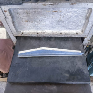
Using a hydraulic press, Malloy then drove the forming block into the aluminum blank, deforming it against a heavy rubber matt. This creased the sheet metal with the basic outline of the new rib.
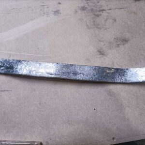
The sheet metal blank for the new flap rib (with the plastic forming block atop it). They are lying on the heavy rubber mat in the hydraulic press following the initial impression. (image via Pioneer Aero Ltd.)
Shaping the Ribs:
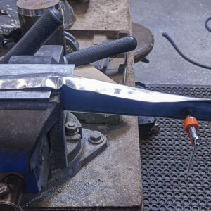
Clamping the forming block and the partially-shaped rib firmly against one another in a vice, Malloy began using a mallet to bend the aluminum further over the plastic. He could only do this part way down each side, as the plastic forming block had insufficient stiffness for such pummeling where the ribs taper to a point.
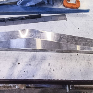
Leaving the tapered ends for later, Jayden returned to shaping the apex and central channel section. The apex needed shrinking to get rid of the wrinkles caused by the excess aluminum which concave bends produce. A shrinking machine sometimes best suits this task, but Jayden also employed a lead slapper, basically a dense piece of softer material which grips the aluminum and folds (shrinks) it in upon itself. After forming the apex, Jayden then worked his way down the channel side away from the center as far as was practical. He then folded up the rib's bottom edge to its proper angle as well.
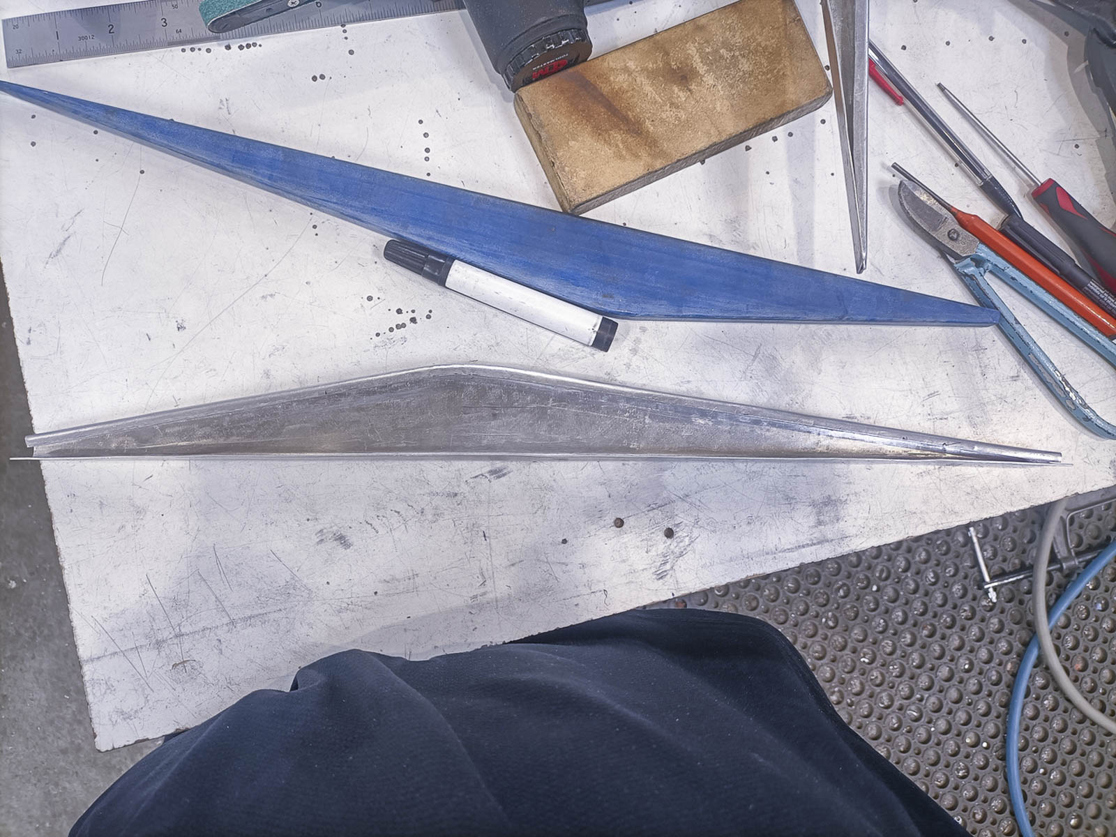
With this completed, Jayden then separated the partially-formed rib from its plastic forming block. To finish shaping the sections where it came to a thin taper, Jayden manufactured two, partial forming blocks (from steel) specifically tailored to each end of the rib. These steel blocks were strong enough to withstand the forming process without bending. Since they were only partial blocks, they were also easy to remove from the rib once it was fully formed. With the rib complete, it was now ready for heat treating to bring it up to the correct temper (strength).
The new rib part of the way through the process of forming its top channel and apex. The wrinkle in the aluminium near the right edge of the vice will be shrunk into itself using both a shrinking machine and a lead slapper. (image via Pioneer Aero Ltd.)
A lead slapper used to help shrink aluminum onto the forming block’s profile. The slapper’s weight and surface area traps the entire section of aluminum sheet being worked, forcing the material to compress in upon itself, thus shrinking it. (image via Pioneer Aero Ltd.)
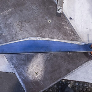
A view part way through the process of shaping the top channel for one of the center flap’s ribs. At this point, the apex has been shrunk into position, while the sides have been formed as far as is practical using the full-sized plastic rib. Jayden manufactured another, partial-length former from steel to finish shaping the thin end of the rib, (image via Pioneer Aero Ltd.)
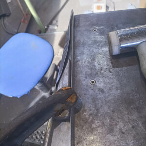
One of the steel forming blocks (partial) used for shaping the thin ends of the ribs being clamped into position prior to commencing the finishing work. (image via Pioneer Aero Ltd.)
Flap Skin Fabrication:
After heat-treating the flap's newly-remanufactured ribs to bring them up to full strength, Jayden began straightening the donor flap's original spar. The spar, sometimes referred to as a beam, forms the dive flap's backbone, providing the bulk of its strength and rigidity. It must conform perfectly to its intended shape, as any kinks will transfer easily to the whole structure and distort it. The dive flap's skin is incredibly thin - just .020" thick - so this same principle must also be applied to each of the joggles on the ribs and stringers, as any deviations will cause visible deformation.
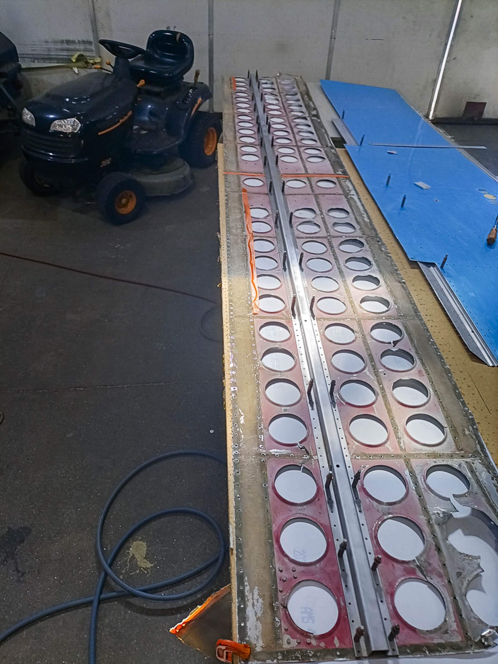
The flap's original skin was too damaged for re-use, but it was sufficiently intact to serve as a template. To fabricate a new skin section which matched the original as closely as possible, Jayden placed the original material atop a new sheet of aluminum. He then back-drilled it to replicate the original attachment holes for the spar, ribs, stiffeners, etc. in the new skin, being careful to limit this process to only those areas of the original skin which remained sufficiently intact.
Trial-fitting Flap Components:
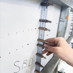
Jayden chose to rebuild the flap on a frame he referred to as a "window jig" - a term which the images below make self explanatory. As Jayden noted, the window jig "keeps [the flap] up off the bench, so that it doesn't get any marks on the skin from swarf or any loose debris. It also makes both sides of the flap accessible, so that I can drill through the holes in the skin onto the new ribs while the skin is held straight. The jig also prevents any twisting from developing as the build progresses."
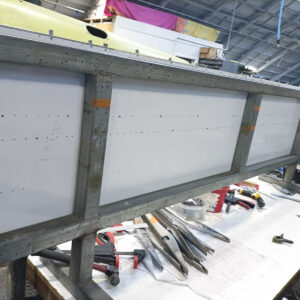
Following back-drilling, the new skin for the center flap is shown here held in place on the window jig. The jig will ensure that the flap remains straight during the restoration process. (image via Pioneer Aero Ltd.)
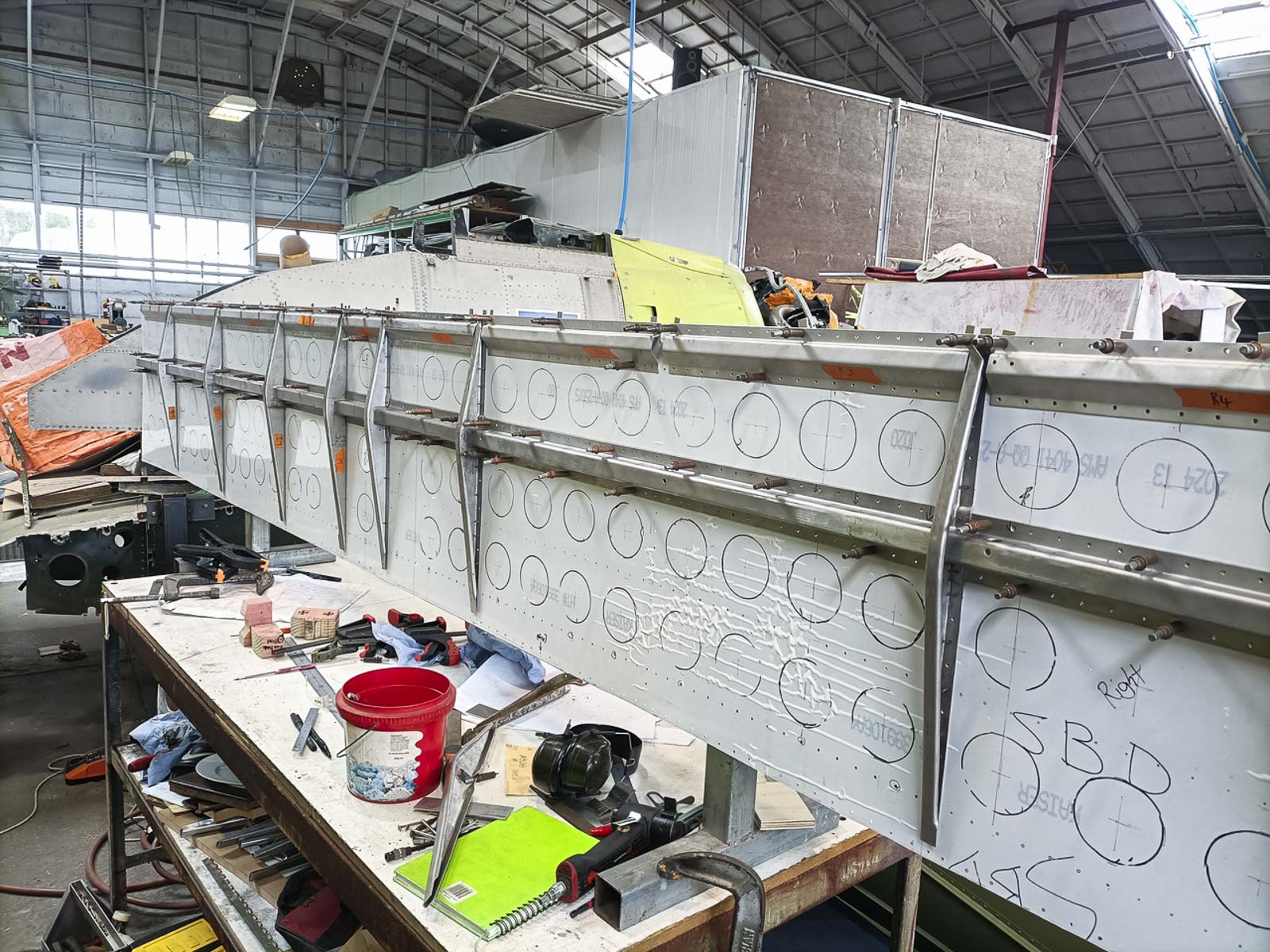
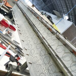
The center flap’s new skin (with lightening hole positions now traced on it) mounted on the window jig part way through the trial-fitting assembly process, with the main and leading edge spars clecoed in place. (image via Pioneer Aero Ltd.)
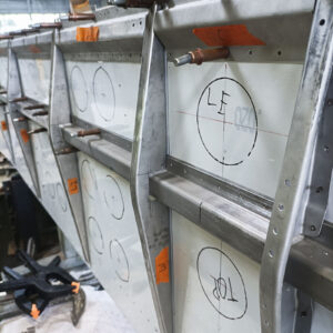
A closeup image of the spar during its trial reassembly, with the ribs now going in place. (image via Pioneer Aero Ltd.)
