Center Section Wing Leading Edges:
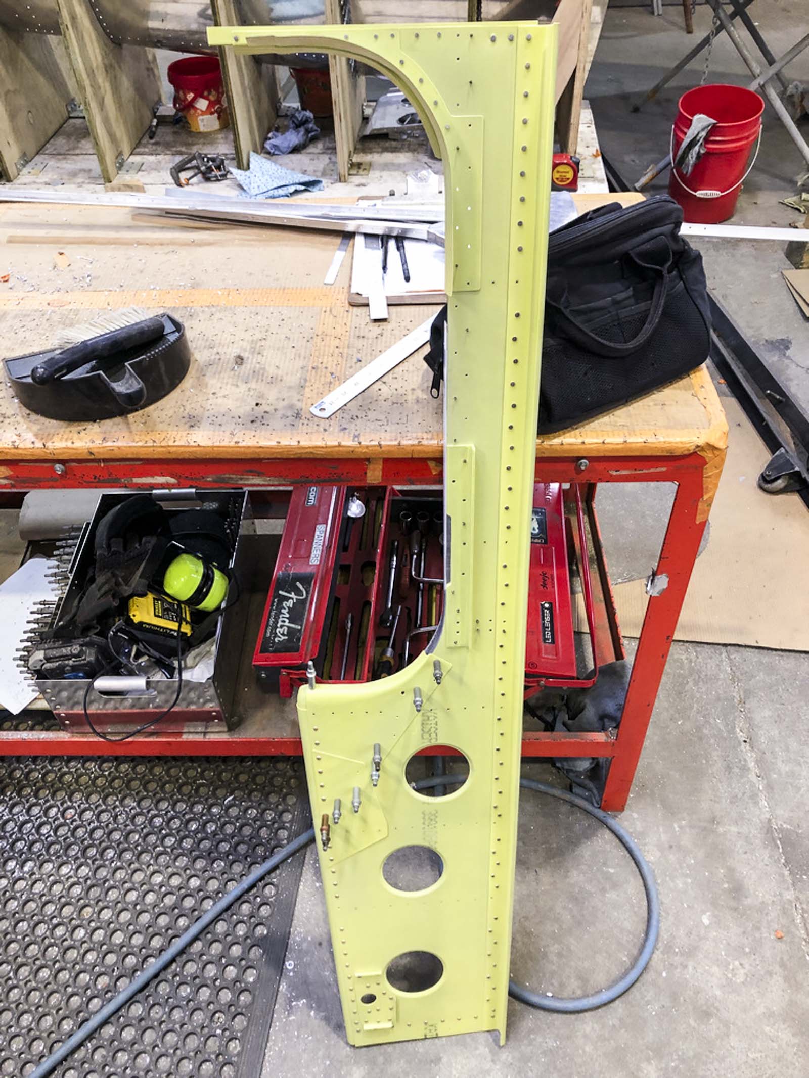
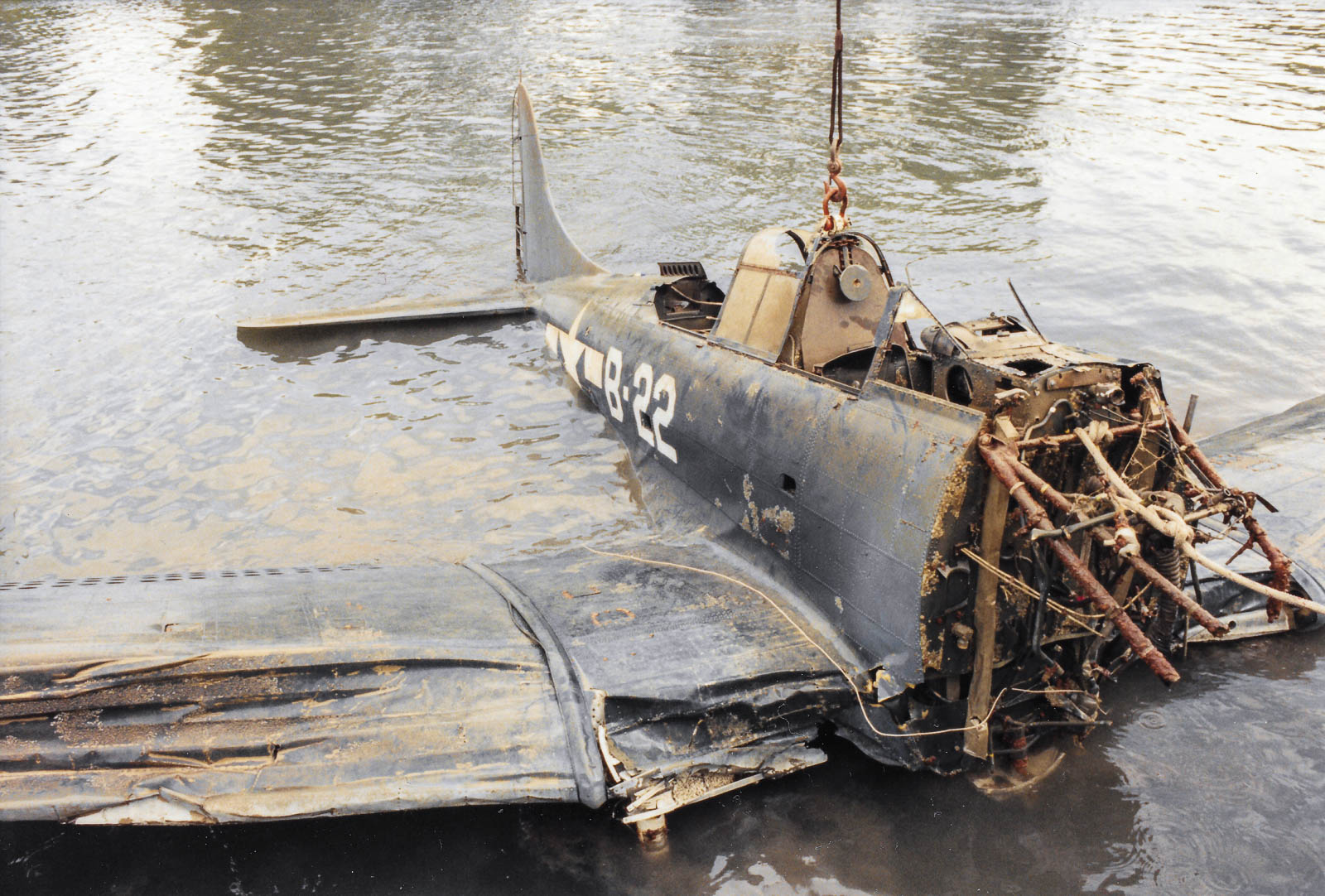
Back in October 2023, the team at Pioneer Aero Ltd. began rebuilding the wing leading edges for the SBD's center section. As the image above reveals, this structure absorbed significant impact damage when the Dauntless ditched into Lake Michigan during January 1944. Consequently, very few of its components survived in restorable condition, so the restoration team has been working hard to manufacture replacements. They tackled the spar web assemblies first, then proceeded to the ribs and leading edge skins; components outlined in the A-24 illustrated parts manual image below.

Leading Edge Ribs:
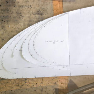
In January, Hadon Smith formed the base shapes for each of the left and righthand leading edge ribs. These components lie between Station 10 and Station 56 on either side of the wing; Station 10 being 10" from the aircraft's center line, with Station 56 being 56" from the same axis. The SBD's original ribs were too badly crushed to even serve as templates for their remanufacture, so the restoration team had to rely upon the Douglas Aircraft lofting drawings to determine the appropriate shapes to apply. Using these documents, Pioneer Aero's engineers created profiles for each rib out of card stock, which they then used as a template for cutting out the necessary forming blocks for shaping replacement components. The images below reveal some of the steps in this process.
The paper templates created from the manufacturer's lofting drawigs to ensure the correct profile from Station 10 through Station 56. The team used these paper templates to cut appropriately profiled forming blocks with which to shape sheet aluminum into new ribs. (image via Pioneer Aero Ltd.)
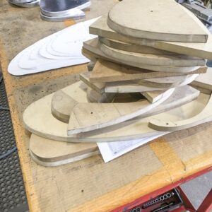
The wooden forming blocks, profiled using the paper templates described in the previous image. This is after fabrication work commenced - newly formed ribs are visible in the background. (image via Pioneer Aero Ltd.)
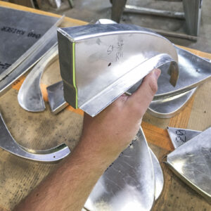
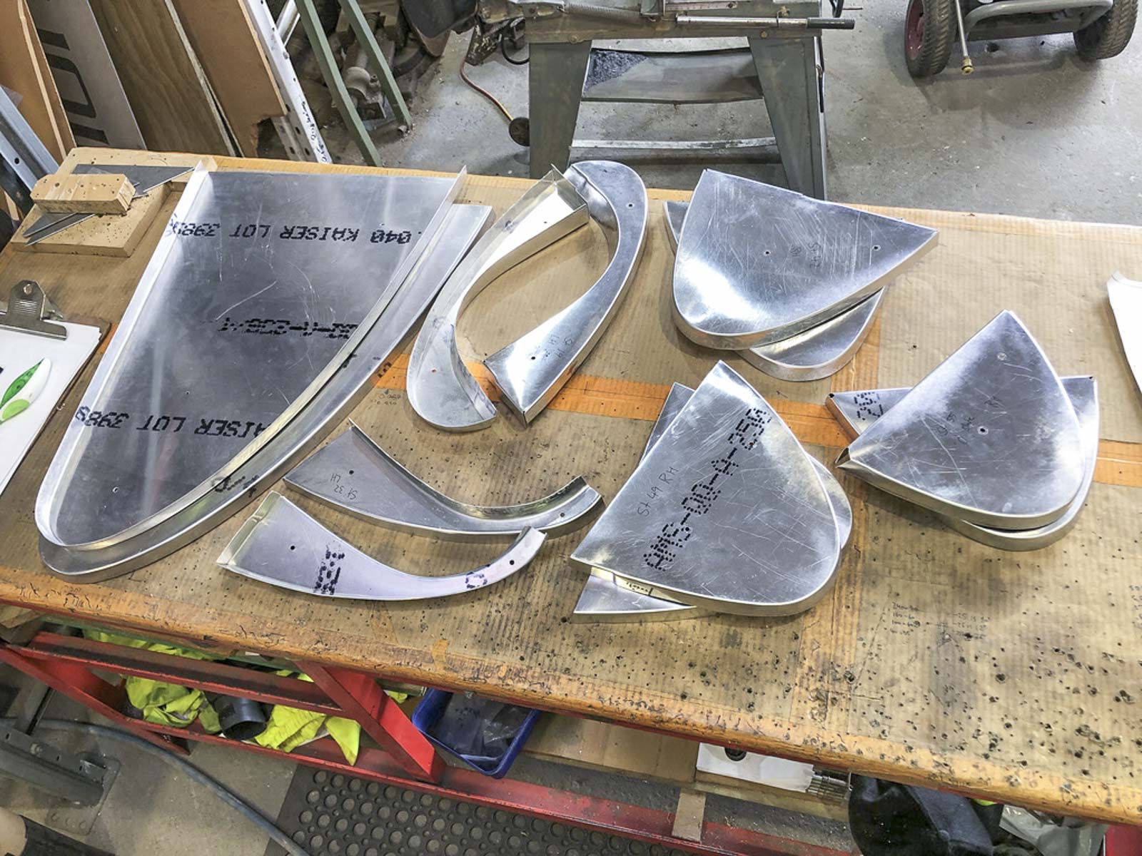
A close up view of one of the newly-formed leading edge ribs. The originals were too badly crushed to serve even as patterns, so the complex curves visible here were recreated purely from the manufacturer’s original lofting drawings. This particular rib is one of a number with an inner curve conforming to the profile described by the forward arch in the wheel well. Other leading edge ribs are visible in the background; this is before any of them had received lightening holes or cutouts for stringers to pass through them. (image via Pioneer Aero Ltd.)
Trial Fitting:
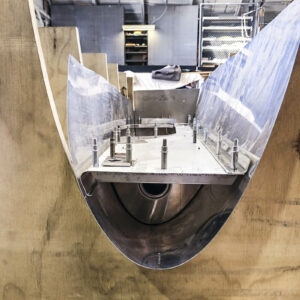
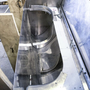
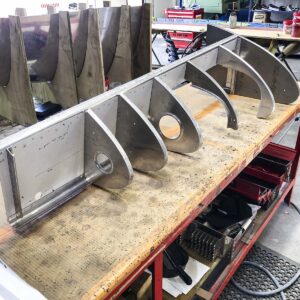
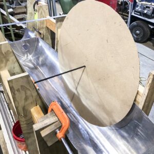
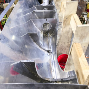
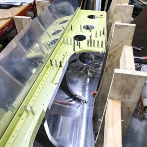
Once the ribs had received their lightening holes, Hadon Smith trial-fitted them against the newly-shaped leading edge skin to ensure they lined up properly. He then clecoed each rib to the leading edge spar and nestled this assembly into the leading edge skin again so he could precisely mark off and remove a cutout for the wheel well. The nose spar has since been painted with primer and mostly riveted together. Hadon also cut slots into each rib for the leading edge stringers. With the ribs now fully-formed, he then sent the parts off for heat treating to bring them up to the correct tensile strength and hardness.
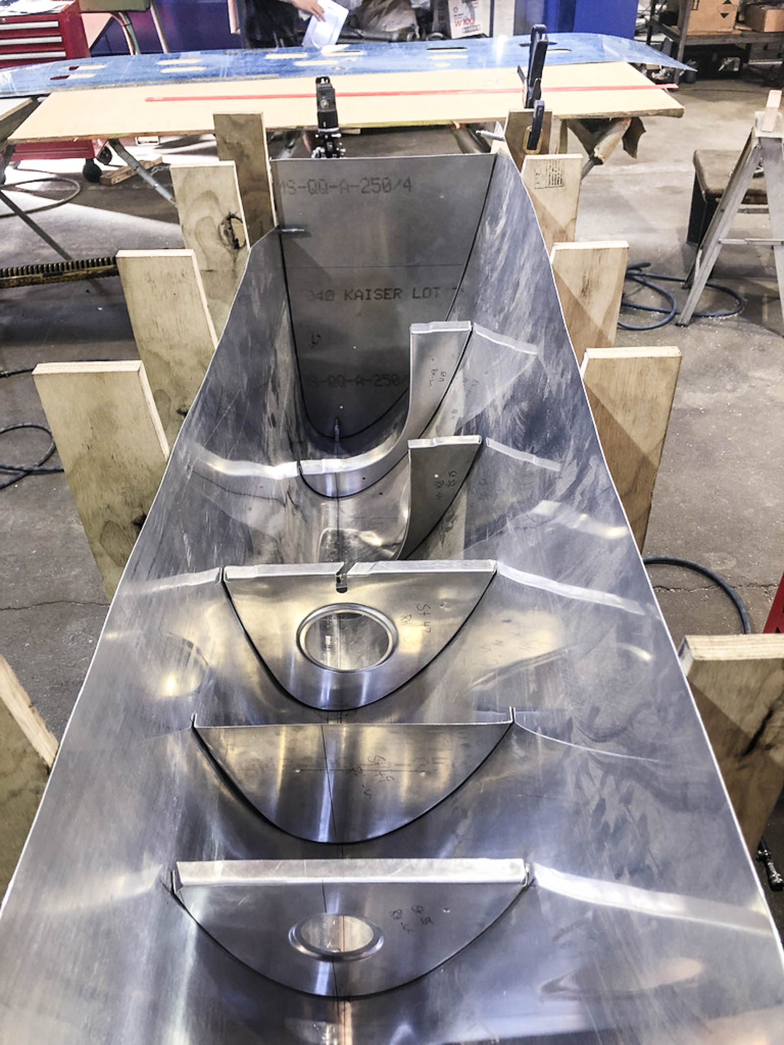
With the ribs properly situated in the leading edge skin, it was then time to trial-fit the leading edge spar against them. (image via Pioneer Aero Ltd.)
A view of the leading edge ribs and spar nestled against the forward skin as seen from the opposite direction to the last image. (image via Pioneer Aero Ltd.)
Marking off the precise cut needed for the wheel well in the leading edge skin. The black rod at the center of the cardboard template would run through the center of the wheel axle. (image via Pioneer Aero Ltd.)
The ribs are now clecoed in place against the leading edge skin. Each rib has also received a cutout to provide an avenue for the stringer seen at the base. Note that the wheel well outline has also been cut from the leading edge skin as well. (image via Pioneer Aero Ltd.)
